emperor grandfather clock manual

The Emperor Grandfather Clock is a timeless piece known for its elegant design and precise engineering. This traditional timepiece combines rich historical charm with modern functionality.

1.1 Historical Background and Popularity

The Emperor Grandfather Clock has a rich history, dating back to its origins as a classic timepiece. Its popularity grew due to its elegant design and precise engineering. Many models were crafted with quality materials and attention to detail, making them sought-after pieces for both functionality and aesthetic appeal. Their timeless charm continues to captivate clock enthusiasts worldwide.

1.2 Key Features and Design Elements

The Emperor Grandfather Clock features a tall, stately cabinet with intricate carvings and a polished finish. Its mechanical movement ensures accurate timekeeping, while the pendulum adds a touch of classic elegance. The clock often includes chime and strike mechanisms for melodious sounds, along with ornate dials and decorative weights that enhance its traditional appeal.

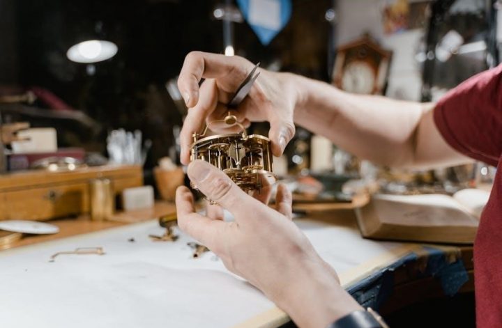
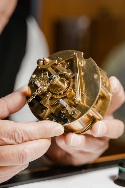
Understanding the Movement of the Emperor Grandfather Clock

The Emperor Grandfather Clock’s movement is its core, controlling timekeeping, striking, and chimes. It relies on weights and a pendulum for power and precision, ensuring smooth operation. Regular maintenance is essential for longevity and accuracy.

2.1 The Role of the Movement in Timekeeping

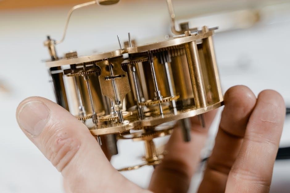
The movement is the heart of the Emperor Grandfather Clock, responsible for accurate timekeeping. It integrates gears, escapements, and a pendulum to measure time precisely. The weights provide power, while the pendulum regulates the release of energy, ensuring consistent time accuracy. Proper alignment and adjustments are crucial for optimal performance and reliability. Regular maintenance ensures the movement operates smoothly over years.

2.2 Differences Between Cable and Chain-Driven Movements

Cable-driven movements use a crank for winding, offering smoother operation and reduced wear. Chain-driven systems require pulling the chain to raise weights, often simpler but less refined. Both systems power the clock’s timekeeping, strikes, and chimes, with cables providing quieter, more consistent energy transfer compared to chains, which can be noisier but equally reliable if properly maintained. Each system has its unique advantages and requirements for optimal performance.

Setting Up Your Emperor Grandfather Clock

Setting up your Emperor Grandfather Clock involves unboxing, leveling, and assembling components like the pendulum and weights. Ensure stability to prevent tipping and ensure accurate timekeeping from the start.

3.1 Unboxing and Initial Preparation

Begin by carefully cutting the nylon bands around the shipping carton and opening the box from both sides. Remove the box containing the product manual and other accessories. Gently slide the clock out of the carton, ensuring it remains upright and stable. Locate the pendulum, weights, and crank, which are packaged separately to prevent damage during transit. Always handle components with care to avoid scratches or bends.

3.2 Leveling and Positioning the Clock

Place the Emperor Grandfather Clock on a firm, level floor to ensure stability. Move it close to its final location and ensure the base is square. Check the floor for evenness and use the built-in levelers or shims if necessary. Proper alignment is crucial for the clock’s stability and accurate operation. Avoid leaning the clock, as this could cause damage or misalignment.

3.3 Hanging the Pendulum and Weights

Gently attach the pendulum to its guide, ensuring it hangs securely. For weights, hang each from the correct position and raise them using a crank or by pulling the chain. Install them carefully to avoid tangling or misalignment. The pendulum should swing freely, while the weights provide consistent power to the clock’s mechanism. Proper installation ensures smooth operation and accurate timekeeping.

Operating the Emperor Grandfather Clock

Start the clock by winding it and hanging the pendulum. Set the time by moving the minute hand counter-clockwise. The chime and strike mechanisms will activate automatically, enhancing the clock’s functionality and charm.

4.1 Starting the Clock and Setting the Time

To start the Emperor Grandfather Clock, wind it using the provided crank, ensuring weights are properly hung. Gently lift and release the pendulum to begin its swing. To set the time, move the minute hand counter-clockwise until the hour and minute hands align with the correct time. Allow the clock to operate for 24 hours before fine-tuning accuracy.

4.2 Understanding the Strike and Chime Mechanisms

The Emperor Grandfather Clock features a mechanical strike and chime system. Hammers strike metal rods to produce distinct tones, creating melodious chimes. The sequence of strikes corresponds to the hour and selected melody. Proper weight alignment ensures accurate timekeeping and chime operation, with the left weight powering the strike, the center for time, and the right for chimes. Correct weight installation is essential for seamless functionality.

Maintenance and Care

Regular cleaning and lubrication are essential for optimal performance. Dust the exterior gently and polish surfaces as needed. Lubricate mechanical parts periodically to ensure smooth operation and longevity.

5.1 Regular Cleaning and Lubrication

Regular cleaning and lubrication are crucial for maintaining your Emperor Grandfather Clock’s performance. Dust the exterior with a soft cloth and polish surfaces using high-quality wood care products. Lubricate mechanical components periodically, such as the movement and pivot points, using a silicone-based spray. This ensures smooth operation and prevents wear. Clean and maintain the pendulum and weights to preserve accuracy and longevity. Regular maintenance helps sustain precise timekeeping and extends the clock’s lifespan. Always follow the manufacturer’s recommendations for cleaning and lubrication to avoid damage. If unsure, consult a professional for assistance.

5.2 Raising Weights and Winding the Clock

Raising the weights and winding the Emperor Grandfather Clock ensures smooth operation. For cable-driven clocks, use the provided crank to wind the weights. For chain-driven models, pull the chain gently until the weights reach their highest position. Perform this process every 7-8 days to maintain accurate timekeeping. Always handle weights carefully to avoid damage. Winding incorrectly can cause mechanical issues, so follow the manual’s instructions precisely. Regular winding keeps the clock running reliably and prolongs its lifespan. Ensure the clock is stationary during this process to prevent accidents. Properly winding and raising weights is essential for optimal performance and longevity of your Emperor Grandfather Clock.

Troubleshooting Common Issues

This section addresses common issues like timekeeping errors, chiming problems, and weight inconsistencies. Regular maintenance and proper setup often resolve these issues. Record your clock’s model number for service.

6.1 The Clock Gains or Loses Time

If your Emperor Grandfather Clock gains or loses time, check the pendulum’s regulation. Move the pendulum bob up or down to adjust accuracy. Allow the clock to run for 24 hours after adjustments to ensure proper timekeeping. Refer to the manual for detailed guidance on regulating the pendulum for optimal performance.

6.2 The Clock Does Not Chime or Strike

If the Emperor Grandfather Clock fails to chime or strike, ensure the chime mechanism is activated and not silenced. Check that the hammers are properly aligned with the chime rods and not obstructed. Verify that the weights are correctly hung and provide sufficient power. Also, ensure the moon dial and night silence features are not interfering with the chime function.

6.3 Weights Do Not Drop at the Same Level

If the weights in your Emperor Grandfather Clock do not drop evenly, check their alignment and ensure they are properly hung. Verify that each weight is correctly positioned on its respective hook and that no obstructions are present. Additionally, ensure the chime and strike mechanisms are not interfering with the weights’ movement. Adjust as needed to maintain synchronized operation.

Advanced Adjustments

Advanced adjustments involve fine-tuning the pendulum for precise timekeeping and aligning the moon dial for accuracy. These tweaks ensure optimal performance and maintain the clock’s elegance and functionality.

7.1 Regulating Timekeeping via the Pendulum

Regulating timekeeping via the pendulum involves adjusting its length to achieve precise accuracy. Gently move the pendulum disk up or down to fine-tune the swing. After 24 hours, check the time accuracy and make minor adjustments if necessary. This process ensures the clock keeps perfect time, maintaining its reliability and elegance over years of use.

7.2 Adjusting the Moon Dial for Accuracy

The moon dial on the Emperor Grandfather Clock tracks the lunar cycle and must be manually adjusted for accuracy; Move the dial to match the current moon phase, ensuring synchronization with the lunar cycle. After adjustment, restart the clock to ensure proper alignment and smooth operation of all mechanisms. Regular checks and adjustments maintain its precision and aesthetic appeal.

Moving and Storing the Clock

When moving or storing the Emperor Grandfather Clock, ensure the pendulum and weights are removed and properly packed to prevent damage. This ensures safe transportation and storage.

8.1 Safe Relocation of the Grandfather Clock

When relocating the Emperor Grandfather Clock, remove the pendulum and weights to prevent damage. Wrap the clock in bubble wrap or a protective cover and ensure it remains upright. Use a sturdy dolly or cart to move the clock, placing it on a soft surface like a blanket. Avoid winding the clock before moving, and ensure all parts are securely packed.

8.2 Preparing the Clock for Long-Term Storage

For long-term storage, disassemble key components like the pendulum and weights, storing them separately in labeled containers. Clean the clock thoroughly and cover it with a breathable fabric or plastic wrap. Place silica gel packets inside to prevent moisture damage. Store the clock in a dry, climate-controlled area away from direct sunlight and extreme temperatures to preserve its condition.

Accessing Internal Components

Access internal parts through the front door, top panels, or back access. Panels are secured with tape or plastic clips. Refer to the manual for detailed instructions.

9.1 Removing and Installing Top Side Panels

Top side panels on the Emperor Grandfather Clock are secured with tape or plastic clips. To remove, gently peel off the tape or release the clip. Lift the panels straight up, ensuring no cables are caught. For reinstallation, align the panels properly and secure them using the original fastening method. Always handle with care to avoid damage.

9.2 Accessing the Movement and Chime Area

Access to the movement and chime area can be achieved through the front door, side panels, or the back access panel. To access, remove the panels as described in the manual. Always ensure the area is secure and free from obstructions. Handle internal components with care to avoid damage. This access allows for maintenance, repairs, or adjustments to the clock’s mechanism.

Product Information and Documentation

The Emperor Grandfather Clock includes essential documentation for operation and maintenance. This documentation provides detailed instructions, model-specific guidance, and troubleshooting tips to ensure optimal performance and longevity of your timepiece.

10.1 Locating the Product Information Label

The product information label is crucial for identifying your Emperor Grandfather Clock model and serial number. It can be found on the back of the clock, inside the top back corner, or behind the dial. This label includes essential details for maintenance, repairs, and ordering parts, ensuring you have everything needed to keep your clock functioning perfectly over the years.

10.2 Recording Model and Serial Numbers for Service

Record the model number and serial number from the product information label for future reference. These details are essential for ordering parts or scheduling service. Store them with your clock’s manual or in a safe place to ensure easy access when needed, avoiding delays in maintenance or repairs for your Emperor Grandfather Clock.

Owning an Emperor Grandfather Clock is a rewarding experience, blending heritage and precision; Proper care ensures lasting performance. Enjoy the timeless elegance and rich chimes it brings to your home.

11.1 Final Tips for Enjoying Your Emperor Grandfather Clock

To fully enjoy your Emperor Grandfather Clock, ensure regular maintenance, such as cleaning and lubrication. Keep the clock level and stable to maintain accurate timekeeping. Always allow the clock to run for 24 hours before adjusting. Avoid placing it near drafts or direct sunlight. Appreciate its craftsmanship and the soothing chimes that enhance your home’s ambiance. Proper care will ensure it remains a cherished family heirloom for generations.

11.2 Where to Find Additional Resources and Support

For additional resources, visit the official Emperor Grandfather Clock website or authorized dealers. Online forums and clock enthusiast communities offer valuable insights. Refer to the product manual or contact customer support for specific inquiries. Websites like theclockdepot.com provide instructional guides and troubleshooting tips. Always ensure you have the model and serial number handy for accurate assistance and parts ordering.

Continue Reading

honeywell pro 5000 installation manual

Welcome to the Honeywell Pro 5000 Installation Manual․ This guide provides a comprehensive walkthrough of installing and configuring your Honeywell Pro 5000 thermostat, highlighting its advanced features and system compatibility for a seamless setup experience․

Overview of the Honeywell Pro 5000 Installation Manual

The Honeywell Pro 5000 Installation Manual is a detailed guide designed to assist users in successfully installing and configuring their thermostat․ It covers essential steps, including wallplate installation, wiring connections, and system testing․ The manual also provides troubleshooting tips and customization options to ensure optimal performance․ By following the instructions, users can ensure compatibility with their HVAC system and enjoy efficient temperature control․ This comprehensive resource is tailored for both DIY enthusiasts and professional installers, making it an indispensable tool for a smooth setup process․

Importance of Proper Installation

Proper installation of the Honeywell Pro 5000 thermostat is crucial for ensuring optimal performance, efficiency, and safety․ Incorrect installation can lead to inaccurate temperature control, increased energy consumption, and potential damage to the system․ Following the manual’s guidelines ensures compatibility with your HVAC system, avoids safety hazards, and prolongs the lifespan of the thermostat․ Correct setup also allows you to customize features for enhanced comfort and energy savings, making it essential to adhere to the instructions provided in the manual for a seamless and reliable operation․

Features of the Honeywell Pro 5000 Thermostat

The Honeywell Pro 5000 thermostat offers advanced features designed for efficiency and comfort․ It includes a backlit display, automatic changeover between heating and cooling, and energy-saving modes․ The thermostat is compatible with a wide range of HVAC systems and supports multi-stage heating and cooling․ Its non-programmable design simplifies operation while maintaining precise temperature control․ Additional features like battery operation and easy installation make it a versatile choice for homeowners seeking a reliable and user-friendly thermostat solution to enhance their home automation experience․

System Requirements and Compatibility

The Honeywell Pro 5000 thermostat is compatible with most standard HVAC systems, including single-stage and multi-stage heating and cooling configurations, ensuring seamless integration into your home setup․

Checking Compatibility with Existing HVAC Systems

Before installing the Honeywell Pro 5000 thermostat, ensure compatibility with your HVAC system․ Verify if your system is single-stage, multi-stage, or heat pump compatible․ Check the voltage requirements, typically 24V AC, and wiring configuration․ Refer to the manual for detailed compatibility charts․ Ensure your HVAC system matches the thermostat’s specifications for proper operation․ If unsure, consult a professional to confirm compatibility and avoid installation issues․

Understanding the Heating/Cooling System Requirements

Understanding your heating and cooling system requirements is crucial for proper Honeywell Pro 5000 installation․ Identify if your system is single-stage, multi-stage, or a heat pump․ Verify the voltage requirements, typically 24V AC, and ensure wiring matches the thermostat’s terminals․ Check if your system supports auxiliary heat or emergency heat․ Properly configuring the thermostat to match your system type ensures optimal performance and avoids operational issues․ Refer to the manual for specific guidelines and compatibility charts to align settings with your HVAC system’s capabilities․

Tools and Materials Needed for Installation

To install the Honeywell Pro 5000 thermostat, gather essential tools and materials․ You will need a Phillips screwdriver for removing the old thermostat and mounting the new wallplate․ A pair of needle-nose pliers may be useful for wiring․ Ensure you have a voltage tester to safely verify power cutoff․ Additional materials include screws, wall anchors, and the provided wallplate․ Refer to the manual for specific wiring labels and system requirements․ Having these tools ready ensures a smooth and efficient installation process․

Preparing for Installation

Before starting, ensure power is turned off at the circuit breaker․ Remove the old thermostat and prepare the wallplate․ Verify system compatibility and review safety guidelines․

Pre-Installation Steps and Safety Precautions

Before installing the Honeywell Pro 5000 thermostat, ensure the power to your HVAC system is turned off at the circuit breaker․ Verify compatibility with your existing system and gather all necessary tools․ Remove the old thermostat carefully to avoid damaging wires․ Handle wiring with caution to prevent electrical shocks․ Double-check the system requirements and ensure all components are compatible․ Familiarize yourself with safety guidelines to avoid injuries or damage during the installation process․ This preparation ensures a smooth and safe setup of your new thermostat․

Disconnecting Power and Old Thermostat Removal

Begin by switching off the power to your HVAC system at the circuit breaker or fuse box․ Verify the power is off using a voltage tester․ Remove the batteries from the old thermostat, if applicable, and gently pull the unit away from the wallplate; Carefully disconnect the wires from the old thermostat, taking note of their labels or colors for reference․ Remove any remaining adhesive or screws holding the old thermostat in place․ Once disconnected, set the old thermostat aside and prepare the area for the new Honeywell Pro 5000 installation․

Preparing the Wallplate and Wiring

Begin by preparing the wallplate for the Honeywell Pro 5000 thermostat․ Remove the battery holder from the wallplate to access the wiring area․ Gently pull the wires through the wire hole in the wallplate, ensuring they are free from any tangles or damage․ Position the wallplate against the wall, aligning it with the marks made during pre-installation․ Secure the wallplate using the provided screws, ensuring it is level and firmly attached․ If necessary, adjust the mounting brackets to accommodate your specific wiring configuration․ This step ensures a clean and professional installation of your new thermostat․

Installation Steps

Mount the wallplate, connect the wires according to the diagram, install the thermostat unit, and test the system to ensure proper functionality and performance․

Mounting the Wallplate

Begin by removing the battery holder from the thermostat․ Carefully pull the wires through the wire hole in the wallplate․ Position the wallplate on the wall, ensuring it is level and properly aligned․ Secure the wallplate using the provided screws․ Make sure the wallplate is tightly fastened to avoid any movement․ Once mounted, plug the wires into their respective terminals on the back of the wallplate․ Double-check that all connections are secure and correctly matched․ This step ensures a stable base for the thermostat unit to function correctly․

Wiring the Thermostat

Start by turning off the power to your HVAC system at the circuit breaker․ Identify each wire and match them to the corresponding terminals on the Honeywell Pro 5000․ Connect the common wire to the C terminal․ For heat-only systems, ensure the R wire is connected to the R terminal․ If your system requires it, remove the R/Rc jumper․ Secure all connections firmly to avoid loose wires․ Refer to the wiring diagram in the manual for specific configurations․ Double-check all connections before restoring power to ensure proper functionality and safety․

Installing the Thermostat Unit

Once the wallplate is securely mounted, align the Honeywell Pro 5000 thermostat unit with the wallplate, ensuring it fits snugly․ Gently push the thermostat onto the wallplate until it clicks into place․ Secure it with the provided screws if necessary․ Make sure the unit is level and firmly attached to the wall․ Insert the batteries into the thermostat, following the polarity indicated․ Turn the power back on and verify that the display lights up and functions correctly․ Refer to the manual for specific alignment and mounting instructions to ensure proper installation․

Testing the System Post-Installation

After completing the installation, turn the power back on at the circuit breaker․ Test the heating, cooling, and fan systems to ensure they operate correctly․ Verify that the thermostat responds to temperature adjustments and mode changes․ Check the display for proper functionality and ensure all features, such as auto-changeover, are working as expected․ Refer to the manual for specific test procedures, including the Installer System Test table, to confirm everything is functioning properly․ This step ensures your Honeywell Pro 5000 thermostat is installed correctly and ready for use․

Configuration and Customization

Configure the Honeywell Pro 5000 to match your HVAC system, customize features like temperature settings and modes, and perform final checks to ensure optimal performance and functionality․

Setting Up the Thermostat for Your System

After installation, configure the Honeywell Pro 5000 to align with your HVAC system type․ Remove the wallplate and access the wiring․ Match the system settings to your heating or cooling configuration․ Use the control panel to select options like heat, cool, or auto mode․ Ensure the thermostat is programmed to your preferred temperature settings․ Refer to the wiring diagram to confirm connections․ Perform a system test to verify functionality․ Customize features such as temperature range and fan operation for optimal performance․ Final checks ensure the thermostat operates seamlessly with your HVAC system․

Customizing Features and Settings

Personalize your Honeywell Pro 5000 thermostat by adjusting settings to suit your preferences․ Set temperature ranges, enable or disable features like auto-changeover, and customize fan operation․ Program schedules or use the hold feature for temporary adjustments․ Explore advanced settings for precise control over heating and cooling cycles․ Ensure all configurations align with your HVAC system capabilities․ Perform final checks to confirm settings are applied correctly and functionality is optimized for your home’s comfort needs․

Final Checks and System Verification

After completing the installation, perform a thorough system test to ensure the Honeywell Pro 5000 thermostat operates correctly with your HVAC system․ Test all functions, including heating, cooling, and fan modes․ Verify that the thermostat responds accurately to temperature adjustments and schedule settings․ Check for proper wiring connections and ensure the display reflects real-time system status․ Review all customized settings to confirm they align with your preferences․ If any issues arise, consult the manual or troubleshooting section for resolution․ Final verification ensures optimal performance and homeowner satisfaction;

Troubleshooting Common Issues

Identify and resolve common installation problems by checking wiring connections, power supply, and thermostat display issues․ Consult the manual or customer support for advanced solutions if needed․

Identifying and Resolving Common Installation Problems

Common issues during Honeywell Pro 5000 installation include wiring mismatches, power supply problems, or display malfunctions․ Start by verifying all connections match the wiring diagram in the manual․ Ensure the C-terminal is properly connected to the transformer’s common side․ If the thermostat doesn’t power on, check circuit breakers or fuses․ For display issues, restart the thermostat or replace batteries if applicable․ Consult the troubleshooting section in the manual or contact Honeywell support for further assistance․ Regular system tests can help identify and resolve heating or cooling malfunctions effectively․

Advanced Troubleshooting Techniques

For advanced issues, check the R/Rc jumper configuration to ensure it matches your system type․ Test the HVAC system by activating heating, cooling, and fan modes separately․ Verify wiring connections for accuracy, focusing on C, R, W, and Y terminals․ If issues persist, use a multimeter to measure voltage at the thermostat terminals․ Ensure the transformer is properly sized for the system․ Consult the manual or Honeywell support for detailed diagnostic procedures and software updates․ Advanced troubleshooting may require professional assistance to resolve complex system incompatibilities or hardware malfunctions effectively․

For further assistance, visit Honeywell’s official website or consult the Honeywell Pro 5000 manual․ Additional support is available through their customer service or authorized dealers․

The Honeywell Pro 5000 installation involves mounting the wallplate, connecting wires according to the system type, installing the thermostat unit, and testing the heating, cooling, and fan functions․ Ensure compatibility with your HVAC system and follow safety precautions․ Refer to the manual for specific wiring diagrams and configuration steps․ After installation, customize settings and verify system operation to ensure optimal performance․ Proper installation ensures energy efficiency and reliable temperature control․

Where to Find Additional Support and Resources

For further assistance, visit Honeywell’s official website at yourhome․honeywell․com for detailed guides, FAQs, and troubleshooting tips․ The Honeywell Pro 5000 manual is also available as a downloadable PDF․ Additionally, contact Honeywell customer support for personalized help․ You can also explore Honeywell’s social media channels and forums for user discussions and expert advice, ensuring you have all the resources needed for a successful installation and operation of your thermostat․

Continue Reading

hampton bay ceiling fan manual remote control

Hampton Bay ceiling fan remote control manuals provide essential guidance for installing, operating, and troubleshooting your fan. They ensure smooth functionality and help resolve common issues effectively.

1.1 Importance of Reading the Manual

Reading the Hampton Bay ceiling fan remote control manual is crucial for ensuring proper installation, operation, and troubleshooting. It provides step-by-step guides, safety precautions, and detailed explanations of features, helping users avoid common mistakes and optimize fan performance.

The manual also serves as a reference for resolving issues like signal interference or remote pairing problems. By understanding the content, users can maximize their fan’s functionality and extend its lifespan through proper maintenance and care.

1.2 Key Features of Hampton Bay Remote Controls

Hampton Bay remote controls offer a range of convenient features, including speed adjustment, light brightness control, and a reverse function for seasonal airflow management. They also include programming capabilities, allowing users to customize settings and ensure compatibility with their ceiling fan models. The remotes often feature dip switches for signal frequency adjustment, ensuring interference-free operation. With intuitive designs and user-friendly interfaces, these remotes provide seamless control over fan functionality, enhancing comfort and energy efficiency in any room.

Installation and Setup

Ensure your ceiling fan is compatible with the Hampton Bay remote system. Set the fan to high speed and turn the light on before installing the remote control.

2.1 Preparing the Ceiling Fan for Remote Control Installation

Before installing the remote control system, ensure your ceiling fan is compatible with Hampton Bay remotes. Verify the fan’s model and check for any existing wall controls. Set the fan to high speed and turn on the light kit if applicable. Disconnect the power supply to the fan at the circuit breaker for safety. Remove any pull chains or existing remote receivers to avoid interference. This preparation ensures a smooth installation process and proper communication between the fan and remote control.

2.2 Step-by-Step Guide to Installing the Remote System

Install the receiver unit inside the fan housing, ensuring it’s securely mounted. Connect the receiver wires to the fan’s motor and light kit according to the manual. Replace the fan’s canopy to conceal the wiring. Install the remote control holder in a convenient location. Set the dip switches on both the remote and receiver to match, ensuring proper communication. Test the remote by turning the fan on/off and adjusting speeds. If issues arise, refer to the troubleshooting section or reset the system by cycling the power.

Basic Operation of the Remote Control

Operating the Hampton Bay ceiling fan remote involves using buttons for on/off, speed adjustment, and light control. Ensure batteries are fresh and dip switches match between the remote and receiver for proper communication. If issues arise, resetting the system by cycling the power or pressing the remote’s reset button may resolve them. Always refer to the manual for specific instructions tailored to your model.

3.1 Speed Control and Light Brightness Adjustment

Hampton Bay ceiling fan remotes offer intuitive speed control, typically with buttons labeled High, Medium, and Low; For light brightness, press and hold the Light button to dim or brighten. Ensure the fan is set to High Speed and the light is On before using the remote. If the remote doesn’t respond, check the batteries and dip switch settings. Regularly cleaning the remote and ensuring proper signal reception will maintain smooth operation. Refer to the manual for model-specific instructions on advanced features like timers or smart integration.

3.2 Understanding the Reverse Function

The reverse function on Hampton Bay ceiling fans allows you to change the fan’s rotation direction, optimizing airflow for different seasons. Press and hold the Reverse button on the remote until the fan changes direction. Ensure the fan is set to the correct direction: counterclockwise for summer to circulate cool air and clockwise for winter to redistribute warm air. Some models may require adjusting a switch on the fan itself. If the reverse function doesn’t work, check if it’s enabled and ensure the remote is functioning properly. Refer to the manual for specific instructions.

Troubleshooting Common Issues

Troubleshooting Hampton Bay ceiling fan remotes involves checking batteries, dip switches, and signal interference. Resetting the fan and remote often resolves connectivity problems. Consult the manual for detailed solutions.

4.1 Remote Control Not Responding

If your Hampton Bay ceiling fan remote isn’t responding, start by checking the batteries. Ensure they are new and correctly installed. Next, verify that dip switches on both the remote and receiver match, as mismatched settings can disrupt communication. If issues persist, reset the system by turning off the circuit breaker for 15 seconds. Also, ensure no devices like garage door openers are interfering with the signal frequency. Finally, consult the manual for specific reset procedures or consider replacing the remote if problems continue.

4.2 Fan Not Turning Off or On

If your Hampton Bay ceiling fan won’t turn on or off, check if the remote control is functioning. Ensure batteries are fresh and correctly installed. Verify that dip switches on the remote and receiver are aligned. If using a wall control, ensure it’s set to the correct speed. Try resetting the system by turning off the circuit breaker for 15 seconds. Also, check if the fan’s pull chain is in the correct position. If issues remain, consult the manual or consider professional assistance to resolve the problem effectively.

4.3 Resetting the Remote and Receiver

Resetting your Hampton Bay ceiling fan remote and receiver can resolve connectivity issues. Start by turning off the fan using the wall switch or circuit breaker for 15 seconds. Turn the power back on and press the remote’s “OFF” button for 30 seconds. This often resets the system. If the fan doesn’t respond, ensure the remote and receiver dip switches are aligned. If issues persist, pairing the remote again by holding the fan and light buttons may be necessary. For severe cases, consider replacing the remote or receiver to restore functionality.

Advanced Features and Customization

Hampton Bay remotes offer advanced features like dip switch settings for signal customization and programming options to tailor fan and light functionality to your preferences.

5.1 Programming the Remote Control

Programming the Hampton Bay remote control involves setting the dip switches on both the remote and the receiver to ensure proper communication. Start by turning off the ceiling fan and ensuring the light kit is in the “on” position. Locate the dip switches on the remote and the receiver, typically found near the batteries or inside the fan’s housing. Set the switches to the same configuration on both devices to synchronize the signal frequency. Once aligned, press and hold the “fan” or “light” button on the remote for 5-10 seconds to complete the pairing process. This ensures seamless control over fan speed and lighting functions. Always refer to the manual for specific instructions, as settings may vary by model. Proper programming is essential for advanced features like speed customization and dimming to function correctly. If issues arise, resetting the remote and receiver may be necessary to restore default settings.

5.2 Adjusting Dip Switches for Signal Frequency

Adjusting dip switches ensures your Hampton Bay ceiling fan remote and receiver communicate correctly. Locate the switches in the remote (near batteries) and the receiver (inside the fan). Set both to the same configuration for proper signal frequency. Start with the fan on high speed and lights on. Test the remote after adjusting. If issues persist, reset by unplugging the fan for 15 seconds. Refer to the manual for specific settings and troubleshooting steps to maintain optimal functionality.

Maintenance and Care

Regular maintenance ensures your Hampton Bay ceiling fan and remote function optimally. Clean the fan blades and remote regularly, replace batteries as needed, and check for signal interference to maintain seamless control.

6.1 Cleaning and Replacing Batteries

Regular cleaning and battery maintenance are crucial for optimal performance. Use a soft cloth to wipe the remote and fan blades, avoiding harsh chemicals. Replace batteries in the remote with new ones of the correct type, ensuring proper orientation. If the remote stops working, check for corroded terminals or weak signals. Cleaning ensures dust doesn’t interfere with infrared signals, while fresh batteries maintain reliable control. Always refer to the manual for compatible battery types and disposal guidelines to ensure longevity and functionality of your Hampton Bay ceiling fan remote system.

6.2 Ensuring Proper Communication Between Remote and Fan

To maintain seamless communication between your Hampton Bay ceiling fan and its remote, ensure the dip switches on both the remote and receiver are synchronized. This synchronization ensures they operate on the same frequency. Regularly clean the remote’s infrared lens to avoid signal obstruction; If issues arise, reset the system by turning off the circuit breaker for 15 seconds. Always use fresh batteries in the remote to prevent weak signals. Proper alignment and unobstructed line of sight between the remote and fan further enhance reliable communication and functionality.

Continue Reading

2011 ford fusion owners manual

Welcome to your 2011 Ford Fusion Owners Manual, your key guide to understanding and maintaining your vehicle. This comprehensive manual covers features, operation, and maintenance tips to ensure optimal performance and safety. Available as a PDF download, it provides detailed instructions for drivers to get acquainted with their car’s capabilities and proper care procedures.

1.1 Structure and Key Sections of the Manual

The 2011 Ford Fusion Owners Manual is organized into clear sections for easy navigation. It begins with an introduction, followed by maintenance schedules, safety features, and troubleshooting guides. Additional sections cover hybrid-specific information, technical specifications, entertainment systems, and warranty details. Appendices provide quick reference guides and technical diagrams, ensuring comprehensive coverage for drivers to optimize their vehicle’s performance and safety.

1.2 Importance of Reading the Manual

Reading the 2011 Ford Fusion Owners Manual is essential for understanding your vehicle’s features, safety systems, and maintenance requirements. It provides critical information for proper operation, troubleshooting, and optimizing performance. By familiarizing yourself with the manual, you can ensure safe driving practices, identify potential issues early, and maximize fuel efficiency. This guide also helps you understand warranty terms and maintain your car’s value, making it a vital resource for every owner.

Maintenance and Troubleshooting Guide

This section provides essential tips for maintaining your 2011 Ford Fusion and troubleshooting common issues. Regular maintenance ensures optimal performance, while troubleshooting guides help resolve problems efficiently.

2.1 Scheduled Maintenance and Service Intervals

Regular maintenance is crucial for your 2011 Ford Fusion’s longevity. Follow the recommended service intervals outlined in the manual, including oil changes every 5,000 to 7,500 miles. Check tire pressure monthly and rotate tires every 6,000 miles. Inspect brakes and battery annually. Refer to page 281 for detailed schedules and procedures to ensure optimal performance and prevent potential issues. Adhering to these intervals helps maintain warranty coverage and overall vehicle health.

2.2 Common Issues and Troubleshooting Tips

Addressing common issues early prevents major repairs. Check for symptoms like uneven tire wear or low battery warnings. For transmission concerns, refer to page 7 of the manual. If issues persist, consult a Ford-certified technician. Regular inspections and timely fixes ensure your Fusion runs smoothly. Troubleshooting tips are detailed in the manual to help you resolve problems efficiently and maintain your vehicle’s performance.

Safety Features and Driving Tips

Your 2011 Ford Fusion is equipped with advanced safety features like airbags and electronic stability control. Always wear a seatbelt and follow safe driving practices to minimize risks.

3.1 Advanced Safety Features in the 2011 Model

The 2011 Ford Fusion includes advanced safety features such as dual front airbags, side airbags, and curtain airbags for enhanced protection. Electronic stability control and anti-lock braking systems are standard, improving traction and preventing skidding. These features work together to provide a safer driving experience, reducing the risk of injury in various collision scenarios.

3.2 Best Practices for Safe Driving

Always wear your seatbelt and ensure all passengers do the same. Follow traffic laws, maintain a safe distance, and avoid distractions like texting. Keep your vehicle well-maintained, checking tire pressure and brakes regularly. Stay alert and adjust driving habits for weather conditions. These practices, combined with the Fusion’s safety features, help ensure a secure and enjoyable driving experience.

Hybrid Model Specific Information

The 2011 Ford Fusion Hybrid combines a gas engine with an electric motor for improved fuel efficiency. This section covers hybrid-specific features, operation, and maintenance tips to maximize efficiency and performance. Refer to the detailed guides within this manual for optimal hybrid driving experiences.

4.1 Hybrid Engine Operation and Benefits

The 2011 Ford Fusion Hybrid operates using a combination of a gasoline engine and an electric motor, optimizing fuel efficiency and reducing emissions. The hybrid system seamlessly switches between engine and electric power, enhancing performance during acceleration and improving efficiency at lower speeds. This innovative technology not only lowers operating costs but also contributes to a more environmentally friendly driving experience, making it a standout choice for eco-conscious drivers.

4.2 Fuel Efficiency and Eco-Friendly Driving

The 2011 Ford Fusion Hybrid excels in fuel efficiency, offering an estimated 41 MPG in the city and 36 MPG on the highway. Eco-friendly driving practices, such as maintaining steady speeds and utilizing the EcoGuide feature, further enhance mileage. Proper tire pressure and timely maintenance also contribute to optimal performance. By following these tips, drivers can maximize efficiency and reduce environmental impact, making the Fusion Hybrid a sustainable choice for daily commuting and long-distance travel.

Technical Specifications and Performance

The 2011 Ford Fusion features a 2.5L I-4 engine, delivering smooth performance and efficiency. Paired with a 6-speed automatic transmission, it ensures a balanced driving experience.

5.1 Engine and Transmission Details

The 2011 Ford Fusion comes with a 2.5L I-4 engine, producing 175 horsepower and 172 lb.-ft. of torque. It features a 6-speed automatic transmission, ensuring smooth shifting and fuel efficiency. Optional engine upgrades include a 3.0L V6 for enhanced power. The transmission is designed for seamless performance, optimizing both city and highway driving experiences.

5.2 Handling and Performance Features

The 2011 Ford Fusion offers responsive handling with its electric power-assisted steering and MacPherson strut front suspension. The rear features a multi-link suspension for a smooth ride. Anti-lock braking ensures reliable stopping power. These features, detailed in the manual, enhance overall performance and driver confidence, providing a balance of comfort and precision on the road.

Entertainment and Infotainment Systems

The 2011 Ford Fusion features the SYNC system for voice commands and navigation. It supports device connectivity and Bluetooth setup for an enhanced user experience.

6.1 SYNC System Overview

The SYNC system in the 2011 Ford Fusion is an advanced infotainment platform designed for seamless connectivity. It supports voice commands, Bluetooth pairing, and navigation, enhancing your driving experience. With intuitive controls, SYNC allows hands-free phone calls, music playback, and integration with compatible devices. This system ensures a connected and enjoyable ride, keeping you entertained and informed on the go.

6.2 Connecting Devices and Bluetooth Setup

Connect your devices to the SYNC system via Bluetooth for hands-free calls and music streaming. Enable Bluetooth on your device, ensure it’s in pairing mode, and follow on-screen prompts. Use voice commands or buttons to complete pairing. This setup enhances safety by minimizing distractions, allowing you to control functions effortlessly. Ensure your device is compatible for optimal performance and a seamless connectivity experience.

Warranty and Support Information

Understand your warranty coverage and explore support options. Contact Ford assistance for inquiries. Utilize Ford SYNC and FordPass for enhanced support and service articles, ensuring optimal your vehicle care.

7.1 Understanding Your Warranty Coverage

Your 2011 Ford Fusion warranty provides coverage for parts and labor under specific conditions. Review the manual for details on duration, mileage limits, and covered repairs. Understanding your warranty ensures protection against unexpected costs and helps maintain your vehicle’s performance. Refer to the manual for terms, conditions, and exclusions to make informed decisions about repairs and maintenance.

7.2 Contacting Ford Support and Assistance

For assistance with your 2011 Ford Fusion, contact Ford Support through their official website or customer service hotline. Utilize FordPass for convenient access to resources, or visit authorized dealerships for personalized help. Additional support materials, including how-to videos and service articles, are available online to address common inquiries and maintenance needs. Reach out to Ford’s dedicated team for reliable guidance and troubleshooting.

DIY Repair and Replacement Guides

This section offers step-by-step instructions for basic repairs and replacements, such as oil changes and air filter replacements, empowering owners to maintain their vehicle confidently.

8.1 Simple Repairs You Can Do Yourself

Learn how to perform basic repairs like oil changes, air filter replacements, and battery checks. These simple tasks can save you money and keep your Fusion running smoothly. Always refer to your owner’s manual for specific instructions and safety tips. Make sure to use the correct tools and materials to avoid damaging your vehicle. Regular DIY maintenance can extend the life of your car and prevent more costly repairs down the road.

8.2 Tools and Equipment Needed

For basic repairs and maintenance, you’ll need tools like a wrench set, screwdrivers, pliers, and a multimeter. A tire pressure gauge and wheel chocks are essential for tire-related tasks. Keep a drain pan and funnel for oil changes, and ensure you have a jack and lug wrench for tire replacements. Always use genuine Ford parts and consult the manual for specific torque specifications to avoid damage. Safety first!

Accessories and Customization Options

Your 2011 Ford Fusion can be personalized with genuine Ford accessories, enhancing style and functionality. Explore customization options to tailor your vehicle to your preferences and needs.

9.1 Genuine Ford Accessories

Genuine Ford accessories for the 2011 Fusion are designed to enhance functionality and style. Choose from a variety of options like floor mats, cargo nets, and roof racks, all engineered to fit perfectly. These accessories ensure quality, durability, and compatibility with your vehicle. They not only improve your driving experience but also maintain your car’s resale value. Visit the Ford website or authorized dealers to explore the full range of genuine accessories tailored for your Fusion.

9.2 Customizing Your Fusion

Customizing your 2011 Ford Fusion allows you to personalize its appearance and functionality. From interior upgrades like seat covers and trim options to exterior enhancements such as alloy wheels and decals, you can tailor your vehicle to your style. Additionally, consider tech upgrades like infotainment systems or driver-assist features to modernize your ride. These modifications not only enhance aesthetics but also improve performance and comfort, making your Fusion truly unique and suited to your preferences.

Where to Find the Manual and Additional Resources

The 2011 Ford Fusion owners manual is available for download as a PDF on Ford’s official website or through authorized dealers. Additional resources include online forums, tutorials, and support articles to help you understand and maintain your vehicle effectively.

10.1 Downloading the PDF Manual

To access the 2011 Ford Fusion owners manual, visit Ford’s official website or authorized dealerships. Navigate to the support section, select your vehicle model, and download the PDF version. This format allows easy access on devices and offline viewing. Ensure to check for the latest updates to get the most accurate information for your vehicle.

10.2 Online Communities and Forums

Engage with online communities and forums dedicated to the 2011 Ford Fusion for shared knowledge and support. Websites like Ford forums and enthusiast groups offer troubleshooting tips, DIY guides, and real-world insights from experienced owners. These platforms foster discussions on maintenance, modifications, and common issues, providing valuable resources to enhance your ownership experience and address specific concerns effectively.

Continue Reading

white rodgers 1f86-344 manual

The White Rodgers 1F86-344 is a digital, non-programmable thermostat offering dual power options and compatibility with single-stage HVAC systems. It is known for its user-friendly design, reliability, and affordability, making it a popular choice for both homeowners and professionals. This thermostat provides precise temperature control and is backed by comprehensive installation and operation manuals, ensuring easy setup and maintenance.

1.1 Overview of the Thermostat

The White Rodgers 1F86-344 is a non-programmable digital thermostat designed for single-stage heating and cooling systems. It offers dual power options, including battery and hardwire capabilities, making it versatile for various installations. With a solid-state microcomputer, it provides accurate temperature control, ensuring consistent comfort. The thermostat features a backlit display for easy readability and is compatible with low-voltage HVAC systems. Its straightforward design and reliability make it a cost-effective solution for homeowners seeking basic temperature regulation without advanced programming features. The device is intended for use with low-voltage systems and is not suitable for line voltage applications.

1.2 Importance of the Manual

The manual for the White Rodgers 1F86-344 thermostat is essential for understanding its features, installation, and operation. It provides detailed step-by-step guides for installing the thermostat, including wiring instructions and compatibility checks. The manual also covers troubleshooting common issues and interpreting error codes, ensuring users can resolve problems quickly. Additionally, it explains how to configure the thermostat for optimal performance and energy efficiency. By following the manual, users can ensure proper setup and maintenance, extending the lifespan of the device. It serves as a valuable reference for both initial setup and ongoing use, making it indispensable for homeowners and professionals alike.

Features of the White Rodgers 1F86-344

The White Rodgers 1F86-344 manual is crucial for understanding thermostat features, installation, and operation. It provides detailed instructions for wiring, compatibility checks, and troubleshooting common issues. The manual ensures proper setup and configuration, helping users achieve optimal performance and energy efficiency. It also serves as a reference for resolving errors and maintaining the device. By following the manual, users can maximize the thermostat’s functionality and extend its lifespan, making it an indispensable resource for both homeowners and professionals.

2.1 Technical Specifications

The White Rodgers 1F86-344 thermostat operates as a non-programmable, single-stage unit, supporting both heating and cooling systems. It features a backlit display for enhanced visibility. The thermostat is dual-powered, compatible with both battery (mV ⎻ 30 VAC) and hardwire (20 — 30 VAC) options. It supports systems with a current rating of 1 ⎻ 1.5 amps. The temperature range is adjustable from 45°F to 99°F, ensuring precise climate control. Designed for low-voltage systems, it is not suitable for line voltage applications. Its solid-state microcomputer ensures accurate temperature regulation, making it a reliable choice for residential HVAC systems.

2.2 Display and User Interface

The White Rodgers 1F86-344 features a backlit digital display, ensuring clear visibility in various lighting conditions. The user interface is designed for simplicity, with intuitive buttons for navigating menus and adjusting settings. The thermostat includes a SYSTEM switch for mode selection and menu navigation, while buttons allow easy temperature adjustments. The digital display provides straightforward feedback, making it easy to monitor and control heating and cooling settings. This interface is optimized for user convenience, offering a seamless experience for both homeowners and professionals. Its clear layout and responsive controls ensure precise temperature management with minimal effort.

2.3 Power Options (Battery and Hardwire)

The White Rodgers 1F86-344 thermostat offers flexible power options, supporting both battery and hardwire connections. The battery option utilizes mV ⎻ 30 VAC, providing convenience for installations without a constant power source. Alternatively, the hardwire option operates on 20 ⎻ 30 VAC, accommodating systems requiring a direct power supply. This dual capability ensures reliability and adaptability, catering to various HVAC setups. The thermostat’s design allows seamless switching between power sources, enhancing its versatility for different environments. This feature is particularly advantageous for users who prefer the freedom of battery operation or the stability of a wired connection, ensuring uninterrupted performance in any setting.

Installation Guide

Remove packing material, connect wires to terminal screws, and ensure compatibility with your HVAC system. Follow step-by-step instructions for a secure and proper installation process.

3.1 Compatibility with HVAC Systems

The White Rodgers 1F86-344 thermostat is designed for compatibility with single-stage heating and cooling systems. It works seamlessly with low-voltage HVAC setups, ensuring reliable performance. The thermostat supports both heating and cooling stages, making it suitable for a wide range of residential systems. Additionally, it is compatible with both battery and hardwire power options, offering flexibility in installation. However, it is not intended for use with line voltage systems, so users must ensure their HVAC system is low-voltage before installation. This compatibility ensures optimal functionality and precise temperature control.

3.2 Step-by-Step Installation Process

Begin by turning off the power to your HVAC system at the circuit breaker or fuse box to ensure safety. Remove the old thermostat and disconnect the wires, taking note of their colors and connections. Mount the new White Rodgers 1F86-344 thermostat base to the wall using the provided hardware. Connect the wires to the appropriate terminals on the base, matching the color codes from your system. Reattach the thermostat faceplate and restore power to the HVAC system. Finally, test the thermostat by switching between heating and cooling modes to ensure proper operation. Follow the manual for detailed wiring instructions.

3.3 Wiring Instructions

When wiring the White Rodgers 1F86-344 thermostat, ensure the system is powered off. Identify the terminals on your HVAC system and match them to the thermostat’s terminals (R, W, Y, G, C, etc.). Connect the wires securely to the appropriate terminals on the thermostat base. If using the battery option, no additional wiring is required. For hardwiring, connect the common (C) wire to the thermostat’s C terminal. Double-check all connections to avoid errors. Refer to the manual for specific wiring diagrams and ensure compliance with local electrical codes. Proper wiring ensures safe and reliable operation of the thermostat. Always test the system after wiring.

3.4 Initial Setup and Configuration

After installation, move the SYSTEM switch to the OFF position. Press and hold the button to access the menu. Use the arrows to navigate through settings like temperature range (45-99°F), system type (heat/cool), and fan operation. Set your preferred defaults, ensuring they match your HVAC system’s capabilities. Save changes by moving the SYSTEM switch back to HEAT or COOL. Test the system to ensure proper operation. This initial setup ensures the thermostat functions correctly with your specific HVAC configuration, providing accurate temperature control and reliable performance. Proper configuration is essential for optimal energy efficiency and comfort. Refer to the manual for detailed guidance.

Programming the Thermostat

The White Rodgers 1F86-344 offers basic and advanced programming options, allowing users to set temperature schedules and customize settings for optimal energy efficiency and comfort.

4.1 Basic Programming Options

The White Rodgers 1F86-344 thermostat provides straightforward programming options, enabling users to set preferred temperature levels for heating and cooling modes. While it is a non-programmable model, it allows for basic adjustments such as setting temperature ranges and switching between heat and cool modes. The interface is user-friendly, with buttons for adjusting temperature and selecting operating modes. This simplicity makes it ideal for users who prefer a no-frills approach to temperature control. The thermostat also features a backlit display for easy readability, ensuring that basic programming tasks can be performed effortlessly. Its design focuses on ease of use and energy efficiency.

4.2 Advanced Settings and Customization

While the White Rodgers 1F86-344 is a non-programmable thermostat, it offers some customization options to enhance user experience. Users can adjust temperature limits and set preferences for heating and cooling modes. The thermostat allows for switching between heat and cool modes manually, and the backlit display provides clear visibility for adjustments. Additionally, the system includes options for fan operation and temperature differential settings. These advanced settings enable users to tailor the thermostat’s performance to their specific needs, ensuring optimal comfort and energy efficiency. The manual provides detailed guidance on accessing and configuring these settings for personalized control. This ensures a balance between simplicity and functionality.

Troubleshooting Common Issues

Troubleshooting the White Rodgers 1F86-344 involves addressing issues like unresponsive displays or temperature inaccuracies. Check power sources, wiring connections, and ensure the thermostat is clean. Consult the manual for detailed solutions and error code interpretations to resolve problems efficiently and maintain optimal performance.

5.1 Common Problems and Solutions

Common issues with the White Rodgers 1F86-344 include a blank or unresponsive display, inaccurate temperature readings, and system errors. For a blank display, check battery levels or hardwire connections. Inaccurate temperatures may result from improper calibration or dirty sensors—clean the thermostat gently. System errors often require resetting the device by turning power off and on. Additionally, ensure wiring is secure and free from damage. Refer to the manual for specific error codes and their meanings. Addressing these issues promptly ensures optimal performance and extends the thermostat’s lifespan.

5.2 Error Codes and Their Meanings

The White Rodgers 1F86-344 thermostat may display error codes like E1, E2, or E3, indicating specific issues. E1 often relates to low battery or power supply problems, while E2 may signify a faulty temperature sensor. E3 could indicate communication errors between the thermostat and HVAC system. These codes guide users to potential issues, enabling quick troubleshooting. Consulting the manual provides detailed explanations and solutions, ensuring the thermostat operates efficiently. Addressing these errors promptly helps maintain consistent temperature control and prevents system downtime.

Maintenance and Care

Regular maintenance ensures optimal performance. Clean the display and check batteries regularly. Refer to subtopics for detailed cleaning and proper battery replacement instructions, ensuring reliability.

6.1 Cleaning the Thermostat

Regular cleaning ensures optimal performance and longevity. Use a soft, dry cloth to gently wipe the display and exterior surfaces. Avoid harsh chemicals or liquids, as they may damage the thermostat. For stubborn smudges or dust, lightly dampen the cloth with water, but ensure it is thoroughly dry before wiping. Clean the display screen carefully to maintain visibility. Avoid touching the screen excessively, as oils from skin can leave residue. If dust accumulates inside, use compressed air cautiously, holding the can upright to prevent moisture damage. Regular maintenance ensures precise temperature control and reliable operation of your White Rodgers 1F86-344 thermostat.

6.2 Battery Replacement and Maintenance

The White Rodgers 1F86-344 thermostat operates on either batteries or hardwire power. For battery-powered models, use 2 AA alkaline batteries (1.5V). To replace batteries, remove the front cover and insert new ones, ensuring correct polarity. Avoid mixing old and new batteries or using rechargeable types. If the display dims or shows a low-battery alert, replace batteries promptly. Clean terminals with a soft cloth to maintain proper contact. For hardwired units, ensure power is off before servicing. Regularly check battery levels to prevent system interruptions. Proper battery maintenance ensures consistent performance and accurate temperature control for your thermostat.

The White Rodgers 1F86-344 thermostat is a reliable, easy-to-use solution for temperature control. Its comprehensive manual and robust features ensure efficient operation, making it a valuable addition to any home.

7.1 Summary of Key Points

The White Rodgers 1F86-344 thermostat is a non-programmable, single-stage digital thermostat designed for compatibility with low-voltage HVAC systems. It offers dual power options, including battery and hardwire, ensuring flexibility in installation. The thermostat features a user-friendly interface with a backlit display for easy temperature adjustments. Its robust design and solid-state microcomputer technology provide precise temperature control and reliability. The manual includes detailed installation, operation, and troubleshooting guides, making it accessible for both professionals and homeowners. With its affordable price and efficient performance, the 1F86-344 remains a popular choice for basic heating and cooling needs.

7.2 Final Thoughts on the White Rodgers 1F86-344

The White Rodgers 1F86-344 thermostat is an excellent choice for homeowners seeking a reliable, non-programmable solution. Its simplicity, combined with efficient performance, makes it ideal for basic heating and cooling needs. The thermostat’s dual power options and backlit display enhance user convenience. While it may lack advanced features, its affordability and ease of use compensate, offering great value for those with straightforward HVAC requirements. With comprehensive manual support, it remains a dependable option for maintaining comfortable indoor conditions without unnecessary complexity.

Continue Reading

gfta scoring manual

The Goldman-Fristoe Test of Articulation (GFTA) Scoring Manual is a comprehensive guide for evaluating speech sound production in individuals. It provides detailed instructions for accurate scoring, ensuring reliable assessment results. The manual supports clinicians in interpreting articulation errors and phonological patterns, aiding in effective speech therapy planning and progress monitoring. It is an essential resource for professionals working with children and adults to assess and improve communication skills.

Overview of the Goldman-Fristoe Test of Articulation (GFTA)

The Goldman-Fristoe Test of Articulation (GFTA) is a standardized assessment tool designed to evaluate speech sound production in children and adults. It measures articulation skills by identifying errors in sound production, such as substitutions, omissions, or distortions. The test includes subtests like Sounds-in-Words and Sounds-in-Sentences, which provide a comprehensive view of articulation abilities. Clinicians use the GFTA to diagnose speech disorders, track progress, and inform treatment plans. It is widely recognized for its reliability in assessing speech sound development across various age groups.

Importance of Accurate Scoring in Speech Assessment

Accurate scoring in speech assessment is crucial for reliable diagnosis and effective intervention planning. It ensures that articulation errors are identified precisely, enabling clinicians to develop targeted treatment strategies. Inaccurate scoring can lead to misdiagnosis or inappropriate interventions, potentially delaying progress. The GFTA scoring manual provides clear guidelines to minimize errors, ensuring consistent and valid results. By adhering to these standards, clinicians can confidently assess speech skills, monitor progress, and make data-driven decisions to support individuals with communication challenges.

Administration of the GFTA

The GFTA requires careful preparation, including gathering test materials and ensuring a quiet environment. Clinicians administer subtests like Sounds-in-Words and Sounds-in-Sentences, following standardized procedures for reliable results.

Preparation and Materials Needed

Administering the GFTA requires specific materials, including the test manual, record forms, and audio equipment for clear stimulus presentation. Clinicians must prepare by reviewing test protocols and ensuring a quiet, distraction-free environment. Additional materials like stimuli cards or digital tools may be used to present test items. Proper preparation ensures accurate and reliable assessment results, adhering to standardized procedures. Familiarity with the test format and materials is essential for effective administration and scoring.

Test Environment and Clinician Requirements

The GFTA requires a quiet, distraction-free environment to ensure accurate results. Clinicians must have strong knowledge of phonetics and speech sound development. They should be trained in standardized testing procedures and familiar with the GFTA-3 format. Proper audio equipment and clear speech are essential for presenting stimuli. Clinicians must maintain professionalism, ensuring the test-taker feels comfortable and understood. Adherence to these requirements ensures reliable and valid assessment outcomes, critical for accurate scoring and interpretation.

Scoring Methods for GFTA-3

The GFTA-3 offers two scoring methods: manual and automated. Manual scoring involves counting articulation errors and referencing the manual for standard score conversion. Automated scoring via Q-global streamlines the process, reducing errors and saving time, while providing detailed reports for clinical interpretation.

Manual Scoring Process

The manual scoring process for the GFTA-3 involves carefully counting articulation errors from the test responses. Each error is tallied, and the total number of errors determines the raw score. Using the scoring manual, clinicians convert this raw score into a standard score based on the individual’s age and gender, ensuring accurate assessment of speech sound production. This method requires attention to detail and adherence to the guidelines provided in the manual to ensure reliable results for diagnostic and therapeutic purposes.

Using Q-global for Automated Scoring

Q-global offers a streamlined approach to scoring the GFTA-3, reducing errors and saving time. Clinicians can easily enter responses into the platform, which automatically calculates raw and standard scores. The system provides detailed reports, including normative comparisons and score summaries. Subscriptions for Q-global are available in 1-, 3-, or 5-year options, offering flexibility for clinicians. While other tablets can be used for data entry, Q-global remains the recommended tool for efficient and accurate scoring, enhancing the assessment process for speech sound production.

Understanding Raw and Standard Scores

Raw scores count articulation errors, while standard scores adjust for age and gender, enabling normative comparisons. Both are crucial for accurate speech assessment and interpretation.

Calculating Raw Scores from Articulation Errors

Raw scores are derived by tallying the total number of articulation errors across all test items. Each error is counted as one point, and the sum represents the raw score. This score reflects the individual’s performance without adjustments for age or gender. Clinicians must carefully review each response, ensuring accuracy in identifying errors. The raw score serves as the foundation for further analysis, requiring conversion to standard scores using age-specific norms provided in the GFTA scoring manual.

Converting Raw Scores to Standard Scores

Converting raw scores to standard scores involves using normative data from the GFTA manual. Standard scores are calculated based on the individual’s age and gender, providing a comparative measure against peers. The manual offers tables to determine percentile ranks and standard deviations. This conversion allows clinicians to interpret performance in a standardized context, facilitating accurate diagnosis and treatment planning. Standard scores are essential for understanding an individual’s articulation abilities relative to normative expectations, ensuring reliable and meaningful assessment outcomes.

Interpreting GFTA Results

Interpreting GFTA results involves analyzing standard scores, comparing performance to age-based norms, and identifying articulation errors and phonological patterns to inform clinical decisions and treatment plans.

Understanding Normative Data and Age-Based Scores

Normative data provides a baseline for comparing an individual’s performance to peers of the same age. Age-based scores are standardized, ensuring accurate interpretation. The GFTA-3 uses norms stratified by age and gender, allowing clinicians to identify articulation delays or disorders. Standard scores indicate how a child’s performance compares to the average, helping diagnose speech sound disorders. Understanding these scores aids in creating targeted intervention plans and monitoring progress over time, making it a critical tool in speech-language pathology practice and assessment.

Identifying Articulation Errors and Phonological Patterns

The GFTA-3 helps identify specific articulation errors and phonological patterns by analyzing speech sound production. Errors such as substitutions, omissions, or distortions are categorized and scored. Phonological patterns, like fronting or simplifying consonant clusters, are also assessed. These analyses provide insights into a child’s speech sound development, aiding in diagnosing speech sound disorders; By pinpointing error types and patterns, clinicians can tailor interventions to address specific needs, ensuring targeted and effective speech therapy strategies for improved communication skills.

Special Considerations in Scoring

Special considerations include scoring adjacent medial consonants separately and addressing stimulability. Clinicians must account for syllable boundaries and updated Record Form designs for enhanced usability and accuracy.

Scoring Adjacent Medial Consonants

When scoring adjacent medial consonants, clinicians must consider syllable boundaries. If phonemes are separated by a syllable boundary, they are scored as separate sounds. For example, in “butter,” the two “t” sounds are treated as distinct articulation points. This rule ensures accurate assessment of speech production skills. The GFTA manual provides clear guidelines and examples, such as Figure 15, to aid in scoring these cases correctly. Accurate scoring is critical for identifying articulation errors and informing targeted intervention strategies.

Handling Stimulability and Sounds-in-Words/Sentences

Stimulability assesses a child’s ability to produce sounds with prompting, providing insights into their potential for improvement. Sounds-in-Words and Sounds-in-Sentences subtests evaluate articulation in context. Clinicians score each sound based on accuracy, noting substitutions, omissions, or distortions. These scores help identify phonological patterns and error types, which are crucial for diagnosis and treatment planning. The GFTA manual emphasizes the importance of distinguishing between stimulable and non-stimulable sounds to guide targeted interventions effectively.

Clinical Applications of GFTA Scores

GFTA scores are essential for diagnosing speech disorders and planning targeted interventions. They guide treatment decisions and monitor progress, ensuring effective communication strategies for individuals with articulation challenges.

Using Scores for Diagnostic Purposes

GFTA scores are instrumental in diagnosing speech sound disorders by identifying articulation errors and phonological patterns. Raw scores, derived from error counts, are converted to standard scores, allowing comparison to normative data. This process helps clinicians determine if a child’s speech skills fall within typical ranges or indicate a potential disorder. Standard scores, adjusted for age and gender, provide a clear benchmark for diagnostic decisions. By analyzing these scores, professionals can pinpoint specific sound errors and developmental delays, guiding accurate diagnoses and targeted interventions.

Informing Treatment Planning and Progress Monitoring

GFTA scores provide valuable insights for developing targeted treatment plans and tracking progress. By identifying specific articulation errors and phonological patterns, clinicians can design interventions tailored to the individual’s needs. Standard scores offer a baseline for measuring improvement over time, enabling adjustments to therapy strategies. Regular progress monitoring using GFTA scores helps assess the effectiveness of interventions and informs decision-making for ongoing or modified treatment approaches. This data-driven process ensures personalized and adaptive care, fostering meaningful advancements in speech development.

Common Challenges in GFTA Scoring

Common challenges include transcription errors, inconsistent scoring criteria, and interpreting complex phonological patterns. Clinician feedback has led to improvements in test design and scoring clarity over time.

Troubleshooting Common Scoring Errors

Common scoring errors include miscounting articulation errors, incorrect conversion of raw to standard scores, and misinterpretation of phonological patterns. Clinicians should double-check tallies, ensure accurate use of normative data, and consult the manual for complex cases. Webinars and training resources can clarify scoring nuances, such as handling adjacent medial consonants and stimulability. Proper training and familiarity with the GFTA-3 scoring process are essential to minimize errors and ensure reliable results for effective speech assessment and intervention planning.

Addressing Clinician Feedback and Test Design Improvements

Pearson has implemented design improvements in the GFTA-3 Record Form based on clinician feedback, enhancing usability and clarity. Updates include a redesigned layout to streamline scoring processes and improve data organization. Additional resources, such as webinars, provide guidance on scoring nuances. These changes reflect Pearson’s commitment to addressing clinician needs and ensuring the test remains a reliable tool for speech assessment. Continuous feedback loops help refine the manual and test design, ensuring they meet evolving clinical demands and improve assessment accuracy.

Resources and Support for GFTA Scoring

Access scoring manuals, webinars, and Pearson Clinical Support for guidance. Utilize Q-global tools for efficient scoring and reporting. These resources ensure accurate and effective GFTA assessment;

Accessing Scoring Manuals and Webinars

The GFTA scoring manual and supporting webinars are available through Pearson Clinical’s official website. These resources provide in-depth training on test administration, scoring, and interpretation. Webinars often cover topics like handling articulation errors and using Q-global for automated scoring. Additionally, the manuals offer detailed instructions for converting raw scores to standard scores, ensuring accurate assessments. Clinicians can access these materials by visiting www.pearsonclinical.com and exploring the GFTA-3 section. Regular updates and new resources are added to support ongoing professional development.

Pearson Clinical Support and Q-global Tools

Pearson Clinical provides extensive support for GFTA-3 users, including access to the scoring manual and Q-global, a digital platform for efficient test administration and scoring. Q-global offers automated scoring, detailed reports, and subscription options for 1, 3, or 5 years. Clinicians can access training materials, webinars, and technical support through Pearson’s website. These tools streamline the assessment process, ensuring accurate and timely results. The platform also supports progress monitoring, making it easier to track improvements in articulation skills over time.

The GFTA Scoring Manual is a vital tool for accurate speech assessment, offering detailed guidelines and resources like Q-global for efficient scoring and progress monitoring.

Best Practices for Effective GFTA Scoring

  • Thoroughly familiarize yourself with the GFTA scoring manual to ensure accurate interpretations.
  • Use Q-global for automated scoring to enhance efficiency and consistency.
  • Double-check manual scoring for errors to maintain reliability.
  • Seek peer reviews or second opinions for complex cases.
  • Stay updated with Pearson webinars and resources for the latest scoring guidelines.
  • Document articulation errors and phonological patterns clearly for progress tracking.
  • Regularly calibrate with colleagues to ensure scoring consistency.
Continue Reading

gravely service manual download pdf free

Gravely service manuals provide essential guides for maintaining, repairing, and operating Gravely equipment. Available for free download as PDFs, these manuals offer detailed instructions, troubleshooting tips, and parts information to ensure optimal performance and safety for professionals and DIY enthusiasts alike.

Overview of Gravely and Its Products

Gravely is a trusted brand specializing in high-quality outdoor power equipment, including lawn mowers, tractors, and utility vehicles. Known for durability and innovation, Gravely products are designed to meet the demands of both residential and commercial users. Their equipment is built to deliver exceptional performance, reliability, and safety. The company offers a wide range of models, each tailored to specific tasks, ensuring users can find the perfect tool for their needs. Gravely service manuals are essential resources for maintaining these machines, providing detailed guidance for optimal functionality and longevity.

Importance of Service Manuals for Maintenance and Repair

Importance of Service Manuals for Maintenance and Repair

Service manuals are crucial for ensuring proper maintenance and repair of Gravely equipment. They provide detailed instructions, troubleshooting guides, and repair procedures, enabling users to address issues effectively. These manuals help maintain safety, prevent costly repairs, and extend equipment lifespan. By following the guidelines, users can diagnose problems accurately and perform repairs confidently. Service manuals also include parts information, making it easier to source components. Whether for routine maintenance or complex fixes, these resources are indispensable for keeping Gravely equipment in optimal condition and ensuring user safety.

Benefits of Using Gravely Service Manuals

Gravely service manuals offer detailed instructions, saving time and money. They provide troubleshooting guides, repair procedures, and parts info, empowering users to maintain and fix equipment confidently.

Access to Detailed Maintenance Instructions

Gravely service manuals provide comprehensive maintenance schedules and step-by-step guidance for routine checks and replacements. Users can access detailed procedures for lubrication, blade sharpening, and belt adjustments, ensuring equipment longevity. These manuals also include diagnostic tips to identify and address potential issues early, preventing major breakdowns. With clear instructions and visual aids, users can perform maintenance confidently, knowing they’re following recommended practices. This resource is invaluable for DIY enthusiasts and professionals alike, offering convenience and accessibility as free downloadable PDFs.

Troubleshooting Guides for Common Issues

Gravely service manuals feature dedicated troubleshooting sections to diagnose and resolve common problems. Users can identify symptoms, such as engine issues or mower malfunctions, and find corresponding solutions. These guides include step-by-step checks for components like spark plugs, air filters, and belts. By addressing issues early, users can prevent costly repairs. The manuals also provide repair procedures and part references, ensuring quick fixes. This resource empowers users to maintain their equipment efficiently, reducing downtime and enhancing productivity with clear and actionable guidance available in free PDF downloads.

Repair Procedures and Parts Information

Gravely service manuals provide comprehensive repair procedures and detailed parts information to help users address equipment issues effectively. These manuals include step-by-step instructions for disassembling, inspecting, and reassembling components. They also list required tools, torque specifications, and part numbers, ensuring accurate repairs. Exploded diagrams further assist in identifying and ordering the correct components. By referencing these resources, users can perform efficient and precise repairs, minimizing downtime and extending equipment lifespan. Additionally, parts manuals are available for free download, offering a convenient solution for maintaining and restoring Gravely equipment to optimal condition.

Types of Gravely Manuals Available

Gravely offers various manuals, including service manuals, owner’s manuals, and parts manuals, each tailored to specific needs. Service manuals provide repair procedures, while owner’s manuals focus on operation and safety. Parts manuals detail component identification, ensuring accurate maintenance and repairs.

Service Manuals for Specific Models

Gravely provides service manuals tailored to specific models, ensuring precise guidance for maintenance and repairs. These manuals, available as free PDF downloads, cover detailed procedures for models like the Promaster 260Z, 915 Zoom, and Atlas JSV 996204. They include troubleshooting, disassembly, and installation instructions, essential for professionals and DIY enthusiasts. Manuals are accessible via sites like GravelyManuals.com and OldGravelys.info, offering comprehensive support for optimal equipment performance. If a specific service manual isn’t available, relevant information is often included in the owner’s manual, ensuring users have the necessary resources.

Owner’s Manuals for Operation and Safety

Gravely owner’s manuals are crucial for safe and effective operation of equipment. These guides, available as free PDF downloads, detail proper usage, safety precautions, and routine maintenance. They cover essential topics like startup procedures, control functions, and troubleshooting common issues. Manuals such as the Gravely ZT48HD Owners Manual emphasize operator safety and optimal performance. Accessible via websites like ManualsDir.com, these resources ensure users can operate their equipment confidently and efficiently, adhering to manufacturer guidelines for longevity and reliability.

Parts Manuals for Component Identification

Gravely parts manuals are indispensable for identifying and sourcing components for repairs. Available as free PDF downloads, these manuals provide detailed diagrams and part numbers, ensuring accurate identification of equipment components. They cover everything from mower blades to engine parts, making it easier to order replacements. Websites like GravelyManuals.com offer comprehensive parts lists, while ManualsDir.com provides additional resources. These manuals are essential for maintaining and upgrading Gravely equipment efficiently, ensuring optimal performance and extending the lifespan of machinery.

Where to Download Gravely Service Manuals for Free

Gravely service manuals can be downloaded for free from www.ariens.com or GravelyManuals.com. These sites offer PDF manuals for various models, ensuring easy access to essential maintenance and repair information.

Official Gravely Website Resources

The official Gravely website, www.ariens.com, provides a comprehensive resource for downloading service manuals. Users can access PDF versions of manuals for various models, ensuring they have the most accurate and up-to-date information for maintenance and repairs. The site also offers an option to purchase printed manuals for those who prefer physical copies. Additionally, if a specific service manual is unavailable, relevant service information is often included in the owner’s manual, making it a one-stop solution for all Gravely equipment needs.

Third-Party Websites Offering Free Downloads

Several third-party websites, such as GravelyManuals.com and ManualsDir.com, provide free access to Gravely service manuals in PDF format. These platforms offer a wide range of manuals, including service, parts, and operation guides, making it easier for users to find the specific documentation they need. Many of these sites are community-driven, with contributions from Gravely enthusiasts and collectors, ensuring a vast library of resources. Users can download manuals directly, often without registration, making it a convenient option for quick access to critical information.

Communities and Forums Sharing Manuals

Online forums and communities, such as those dedicated to Gravely enthusiasts, often share service manuals and guides for free. These platforms are maintained by passionate users and collectors who contribute scanned and digitized manuals, ensuring accessibility for everyone. Websites like ManualsDir.com and community-driven forums provide direct links to download PDF manuals, fostering a supportive environment for Gravely equipment owners. These resources are particularly valuable for models with limited official support, keeping the legacy of Gravely machinery alive through collaborative efforts.

How to Download Gravely Manuals

Gravely service manuals are available as free PDF downloads. Select the correct manual for your model, then download and save it for easy access.

Steps to Identify and Select the Correct Manual

To download the right Gravely manual, start by identifying your equipment’s model and serial number. Visit trusted sites like GravelyManuals.com or ManualsDir.com and search for your specific model. Browse the available manuals, ensuring the document matches your equipment. Check the manual’s content to confirm it covers maintenance, repair, or operation. Once verified, proceed to download the PDF file for free. Always ensure the manual is complete and relevant to avoid confusion during repairs or maintenance.

Process of Downloading and Saving PDF Files

Visit trusted websites like GravelyManuals.com or ManualsDir.com and locate your desired manual. Click the download link to initiate the process. Depending on the file size, the download may take a few moments. Once complete, the PDF will open in your browser or default PDF viewer. To save, click the “Save” or “Download” button in the viewer. Choose a folder on your device and name the file for easy access. Ensure Adobe Reader or a compatible viewer is installed to open and view the manual offline.

Tips for Using Gravely Service Manuals Effectively

Use the index to quickly locate specific information, understand technical symbols, and follow step-by-step guides for efficient repairs and maintenance of your Gravely equipment.

Navigating the Manual for Specific Information

Navigating a Gravely service manual is straightforward once you understand its structure. Start by reviewing the table of contents or index to quickly locate sections relevant to your needs. Use keywords or model-specific details to find diagnostic procedures, maintenance schedules, or repair instructions. Many manuals include visual diagrams and charts to guide you through complex tasks. For digital versions, utilize the search function to instantly find topics like troubleshooting or parts replacement. This ensures you efficiently access the information necessary for your equipment’s upkeep and repair, saving time and effort.

Understanding Technical Terminology and Symbols

Gravely service manuals often include specialized terminology and symbols that may require clarification. Familiarize yourself with common terms like “diode,” “rectifier,” and “interlock switch” to better understand instructions. Symbols such as wrench icons for maintenance or exclamation marks for safety alerts are frequently used. Many manuals include a glossary or legend section explaining these symbols and terms. Understanding this terminology ensures accurate execution of procedures, enhances safety, and avoids costly mistakes. Referencing these explanations helps users decode complex instructions, making repairs and maintenance more efficient and effective for all skill levels.

Troubleshooting Common Issues with Manuals

Common issues include slow downloads, incomplete files, or missing information. Ensure a stable internet connection, check file size, and verify manual selection for accuracy.

Resolving Download Problems

Download issues can arise due to slow speeds or incomplete files; Ensure a stable internet connection and sufficient storage space. Large files may take time; be patient. Use a compatible browser and Adobe Reader for PDFs. If a file fails to open, check its download location or try a different browser. Verify the file size matches the source to ensure completeness. If issues persist, restart your device or clear browser cache. Enabling JavaScript may also resolve access problems on certain sites. Always confirm the manual’s compatibility with your model for proper functionality.

Addressing Missing or Incomplete Information

If a downloaded manual lacks pages or details, cross-reference with the official Gravely website or forums. Community platforms like GravelyManuals.com often have comprehensive collections. Contact support or dealers for assistance. Ensure the correct model-specific manual is selected, as information varies. Regularly updated versions may resolve gaps. Engage with user communities for shared resources or alternative sources. Always verify the manual’s version and publication date to ensure accuracy and relevance for your equipment needs. This approach helps maximize the utility of the available documentation.

Gravely service manuals are indispensable resources for owners, offering free, detailed guidance for maintenance and repair. Accessing these manuals ensures optimal equipment performance and user safety.

Final Thoughts on the Importance of Service Manuals

Gravely service manuals are vital resources for owners, providing detailed guidance for maintenance, repair, and operation. They empower users to perform tasks confidently, ensuring safety and equipment longevity. Access to free PDF downloads simplifies obtaining these manuals, while comprehensive troubleshooting and parts information enhance problem-solving. By leveraging these resources, users can maximize their equipment’s performance and lifespan. Gravely’s commitment to making manuals available underscores their dedication to customer support and DIY accessibility, making them indispensable for both professionals and enthusiasts.

Encouragement to Utilize Available Resources

Take advantage of free Gravely service manuals to enhance your equipment’s performance and longevity. These resources provide comprehensive guidance for maintenance, repair, and operation, ensuring safety and efficiency. By downloading PDF manuals, you gain access to detailed instructions, troubleshooting tips, and parts information, empowering you to address issues confidently. Explore the wealth of available materials, including owner’s and parts manuals, to maximize your equipment’s potential. Utilizing these resources not only saves time but also ensures your Gravely machinery operates at its best, supporting both professional and DIY efforts effectively.

Continue Reading

arcoaire furnace manual

Arcoaire furnace manuals provide comprehensive guides for installation, operation, and troubleshooting․ These resources ensure optimal performance and safety, covering technical specifications, maintenance, and warranty details․

Overview of Arcoaire Furnace Models and Their Manuals

Arcoaire offers a variety of furnace models, each accompanied by detailed manuals․ Models like the A Series, OLR098A12A, and N9MP1 provide user manuals, service guides, and installation instructions․ These documents cover technical specifications, such as BTU ratings and AFUE efficiency levels, ensuring compatibility with different HVAC systems․ Specific models, like the Rpj II Furnace, include parts diagrams and troubleshooting guides․ Manuals are available in PDF formats, making them easily accessible for download․ Whether for installation, maintenance, or repair, Arcoaire furnace manuals cater to both homeowners and professionals, offering comprehensive support for optimal performance and safety․

Understanding the Importance of the Arcoaire Furnace Manual

The Arcoaire furnace manual ensures optimal performance, safety, and efficient operation․ It provides essential troubleshooting guidance and helps maintain the furnace’s longevity and reliability effectively․

Why Reading the Manual is Essential for Optimal Furnace Performance

Reading the Arcoaire furnace manual is crucial for optimal performance, as it provides detailed instructions tailored to specific models․ It ensures users understand proper installation, operation, and maintenance procedures, maximizing efficiency and safety․ The manual highlights technical specifications, troubleshooting tips, and safety precautions, helping users address common issues promptly․ By following the guidelines, users can extend the furnace’s lifespan and maintain its performance․ Additionally, the manual serves as a reference for compatibility with other HVAC systems, ensuring seamless integration and operation․ Adhering to the manual’s instructions also helps prevent potential hazards and ensures compliance with safety standards, making it an indispensable resource for homeowners․

Key Components of the Arcoaire Furnace Manual

The Arcoaire furnace manual includes installation instructions, technical specifications, troubleshooting guides, maintenance schedules, and safety precautions, ensuring comprehensive understanding and efficient operation of the furnace system․

Major Sections and Information Included in the Manual

The Arcoaire furnace manual is divided into key sections, including installation instructions, technical specifications, troubleshooting guides, and maintenance schedules․ It also covers safety precautions, warranty details, and emergency shutdown procedures․ The manual provides detailed diagrams, part lists, and operational guidelines to ensure proper setup and usage․ Additional sections address compatibility with HVAC systems, fuel-to-air mixture optimization, and high-altitude adjustments․ Users can find clear instructions for addressing common issues and performing routine maintenance tasks to maintain efficiency and safety․ The manual serves as a complete reference for homeowners and technicians, ensuring optimal furnace performance and compliance with safety standards․

Installation and Setup Instructions

The manual provides a step-by-step guide for installing your Arcoaire furnace, including pre-installation checks, wiring diagrams, and configuration settings to ensure a safe and proper setup․

Step-by-Step Guide to Installing Your Arcoaire Furnace

Installing an Arcoaire furnace requires careful planning and adherence to the manual’s instructions․ Begin by preparing the installation site, ensuring proper venting and electrical connections․ Next, unpack and inspect the furnace for any damage․ Follow the wiring diagram to connect the thermostat and other components․ Secure the furnace in its designated location and connect the gas and ductwork․ Finally, test the system to ensure everything operates smoothly and safely․ Always refer to the manual for specific details and safety precautions to avoid any installation issues․

Pre-Installation Checks and Requirements

Before installing your Arcoaire furnace, ensure the site meets all safety and technical requirements; Check for proper venting, combustion air supply, and electrical connections․ Verify gas line compatibility and ensure the area is clear of obstructions․ Review local building codes and manufacturer specifications․ Conduct a thorough inspection of the furnace for any damage or defects․ Ensure all necessary tools and materials are available․ Properly plan the ductwork layout and connections․ Finally, confirm that all safety precautions, such as shutdown procedures, are understood and accessible․ Compliance with these steps ensures a safe and efficient installation process․

Troubleshooting and Maintenance Tips

Regularly check filters, ensure proper airflow, and inspect for wear or damage․ Address issues promptly to maintain efficiency and safety, following manual guidelines for best results․

Common Issues and How to Address Them

Common issues with Arcoaire furnaces include ignition failures, inconsistent heating, and error codes․ Ignition problems may stem from faulty burners or clogged vents․ Inconsistent heating could be due to improper airflow or malfunctioning thermostats; Error codes often indicate specific malfunctions, which can be diagnosed using the manual․ Regular filter cleaning and duct inspections can prevent many issues․ Always ensure proper ventilation and follow the manual’s troubleshooting steps․ If problems persist, contacting a certified technician is recommended to avoid further damage or safety hazards․ Addressing these issues promptly ensures optimal performance and extends the furnace’s lifespan․

Regular Maintenance Tasks to Ensure Efficiency

Regular maintenance is crucial for ensuring your Arcoaire furnace operates efficiently and safely․ Start by cleaning or replacing air filters monthly to improve airflow and reduce strain on the system․ Inspect vents and ducts for blockages or leaks, sealing them as needed․ Check the burner compartment for dirt or debris and ensure proper gas flow․ Schedule annual professional tune-ups to inspect internal components and address potential issues early․ Additionally, monitor the furnace’s performance and keep the area around it clear of obstructions․ Following these steps helps maintain optimal efficiency, reduces energy bills, and prolongs the furnace’s lifespan․

Technical Specifications and Compatibility

Arcoaire furnaces offer high-efficiency models with up to 92․1 AFUE, ensuring energy savings․ They are compatible with natural or propane gas, making them versatile for various HVAC systems․

Understanding the Furnace’s Technical Details

Arcoaire furnaces are designed with advanced features like high-efficiency AFUE ratings, multi-stage heating, and variable-speed blowers․ Models such as the 92․1 AFUE series offer significant energy savings compared to older systems․ Technical details include compatibility with natural or propane gas, making them adaptable to different setups․ The furnaces are also built with durable components, ensuring long-lasting performance․ Understanding these specifications helps homeowners make informed decisions, optimizing their heating needs while reducing operational costs․ Proper installation and maintenance, as outlined in the manual, are crucial for maximizing efficiency and ensuring safety․

Compatibility with Other HVAC Systems

Arcoaire furnaces are designed to integrate seamlessly with various HVAC systems, enhancing overall home comfort․ They can be paired with heat pumps, air purifiers, and thermostats for a unified heating and cooling solution․ Compatibility with both natural gas and propane ensures flexibility in fuel sources․ The furnaces also work well with smart home devices, allowing for remote monitoring and energy management․ Proper installation, as per the manual, ensures that all components function together efficiently, providing balanced airflow and consistent temperatures․ This compatibility makes Arcoaire furnaces a versatile choice for modern households seeking comprehensive climate control․

Safety Precautions and Warnings

Always follow safety guidelines in the Arcoaire furnace manual to avoid hazards․ Ensure proper ventilation, secure gas connections, and keep flammable materials away․ Adhere to shutdown procedures in emergencies․

Important Safety Information for Furnace Operation

Always ensure proper ventilation and combustion air supply as outlined in the manual to prevent carbon monoxide risks․ Keep flammable materials away from the furnace․ Never operate the furnace with damaged or disconnected venting systems․ Ensure all gas connections are secure and leak-free․ Avoid overloading the furnace or adjusting internal components without professional guidance․ Keep children and pets away from operating controls․ Regularly inspect the furnace for signs of wear or damage․ Follow shutdown procedures in case of emergencies or unusual odors․ Adhere to all local safety codes and manufacturer recommendations for safe furnace operation․

Emergency Procedures and Shutdown Instructions

In case of an emergency, immediately turn off the furnace’s power and gas supply․ Do not attempt repairs yourself․ Contact a certified technician to address issues like gas leaks, unusual noises, or malfunctions․ If you smell gas, evacuate the area and open windows for ventilation․ Never restart the furnace until it’s deemed safe by a professional․ For emergency shutdown, locate the main power switch and gas valve, following the manual’s specific instructions․ Refer to the manual for model-specific procedures, such as those outlined in the OLR098A12A or N9MP1 furnace manuals․ Always prioritize safety and follow manufacturer guidelines․

Warranty and Customer Support

Arcoaire furnaces come with comprehensive warranties covering parts and labor․ For support, contact their customer service via phone or online resources for assistance with manuals or repairs․

Understanding Your Furnace Warranty

Arcoaire furnace warranties provide coverage for parts and labor, ensuring protection against defects․ The warranty period varies by model, typically ranging from 5 to 10 years․ Registration is often required for activation․ Extended warranties may be available for added protection․ The manual details coverage specifics, including what is included and excluded․ Understanding your warranty helps maximize protection and ensures compliance with terms․ Always review the manual for precise warranty conditions to avoid unintended voids․ This section is crucial for homeowners seeking long-term peace of mind and financial security for their furnace investment․

How to Contact Arcoaire Customer Support

Arcoaire customer support is accessible through multiple channels to assist with furnace-related inquiries․ You can reach their team via phone, email, or through the official website․ Live chat options are also available for quick resolutions․ For efficient support, have your furnace model number and serial number ready․ Visit the Arcoaire website to find contact details and support resources․ Additionally, the manual provides specific instructions for troubleshooting and maintenance, which can often resolve common issues․ Representatives are available to address warranty questions, technical concerns, and repair needs․ Contacting Arcoaire support ensures professional guidance and timely solutions for optimal furnace performance and longevity․

Continue Reading

aprilaire e100 installation manual

Safety Precautions and Instructions

Always read and follow all safety instructions before installation. Disconnect electrical power to avoid shock. Handle sharp edges with care to prevent injury. Ensure proper installation to avoid property damage or injury. Improper installation or maintenance may cause serious issues. Refer to the manual for detailed safety guidelines and warnings.

1.1. General Safety Guidelines

Always follow general safety guidelines to ensure safe and proper installation. Disconnect electrical power before starting to avoid electric shock. Handle sharp edges with care to prevent injury. Read the manual thoroughly before proceeding. Use appropriate protective equipment. Ensure proper installation by authorized personnel to prevent property damage or injury. Adhere to all local safety regulations and manufacturer instructions to avoid serious potential hazards.

1.2. Electrical Safety Warnings

Always disconnect electrical power before starting installation to avoid electric shock. Ensure the unit is properly grounded to prevent hazards. Use the correct voltage as specified in the manual. Follow all wiring instructions carefully to avoid electrical issues. Never attempt to modify or bypass safety features. Improper electrical connections can lead to serious injury or damage. Ensure all connections are secure and meet local electrical codes.

1.3; Handling and Installation Hazards

Handle the unit with care‚ as sharp edges may cause cuts. Use proper lifting techniques to avoid injury. Ensure the dehumidifier is installed on a level surface to prevent tipping. Avoid over-tightening connections to prevent damage. Improper installation may lead to water leaks or structural issues. Always follow the manual’s instructions for safe handling and installation procedures.

Understanding the Aprilaire E100 Dehumidifier

The Aprilaire E100 is a professional-grade‚ whole-house dehumidifier designed to control humidity and improve indoor air quality. It features a powerful blower and energy-efficient operation‚ integrating seamlessly with HVAC systems for optimal performance and comfort.

2.1. Product Overview and Key Features

The Aprilaire E100 is a professional-grade‚ whole-house dehumidifier designed to effectively manage humidity levels in homes. With a capacity of 100 pints per day‚ it ensures efficient moisture removal. Key features include energy-efficient operation‚ seamless integration with HVAC systems‚ and a built-in blower for optimal airflow. Optional remote control compatibility enhances convenience‚ making it a comprehensive solution for indoor air quality management.

2.2. Technical Specifications and Compatibility

The Aprilaire E100 operates at 120 volts with a power consumption of 420 watts. It is compatible with standard HVAC systems and requires a dedicated 15-amp circuit. The unit measures 33 inches in height and 16 inches in width‚ ensuring easy installation in most spaces. Its compatibility with Aprilaire controls like the Model 8620 Thermostat enhances system integration and performance efficiency.

System Requirements and Compatibility

The Aprilaire E100 requires a 120V‚ 15-amp dedicated circuit and is designed for integration with standard HVAC systems. It is compatible with Aprilaire controls and ventilation systems‚ ensuring seamless operation and enhanced performance when connected to the home’s existing ductwork and electrical infrastructure.

3.1. Electrical Requirements

The Aprilaire E100 requires a 120V‚ 15-amp dedicated circuit. Ensure a properly grounded outlet is used. Install in accordance with local electrical codes and the unit’s wiring diagram. Avoid using extension cords or shared circuits to prevent performance issues or safety hazards. Always disconnect power before servicing to ensure safe operation and maintenance.

3.2. Ducting and HVAC System Compatibility

The Aprilaire E100 is designed to integrate with your home’s HVAC system. Ensure compatible ducting sizes and configurations for optimal airflow. Use appropriate plenum adapters and connections to maintain system performance. Proper installation ensures balanced humidity control and efficient operation throughout your home. Refer to the manual for specific ducting recommendations and compatibility guidelines.

Installation Process

Read the manual thoroughly before starting. Ensure the unit is properly prepared and leveled. Follow step-by-step instructions for secure installation and connections to your HVAC system.

4.1. Pre-Installation Steps and Preparation

Before installation‚ ensure all components are included and undamaged. Read the manual carefully to understand the process. Disconnect power to the HVAC system for safety. Ensure the area is clear and well-ventilated. Check local building codes and regulations. Verify compatibility with your HVAC system and ductwork. Plan the installation layout to avoid obstructions and ensure proper airflow.

4.2. Physical Installation of the Unit

Mount the dehumidifier securely in the designated area‚ ensuring it is level and stable. Connect the ductwork to the unit’s inlet and outlet ports‚ sealing all joints properly. Use the provided hardware to secure the unit to the floor or wall for stability. Handle sharp edges with care to avoid injury. Follow the manufacturer’s guidelines for proper placement and alignment to ensure optimal performance and safety.

4.3. Connecting the Dehumidifier to the HVAC System

Connect the dehumidifier to your HVAC system by attaching the ductwork to the unit’s inlet and outlet ports. Ensure all connections are secure and sealed properly to prevent air leaks. Refer to the wiring diagram for integrating the dehumidifier with your HVAC controls. Use compatible ducting materials and verify system compatibility before finalizing connections. Check for any kinks or blockages in the ductwork to ensure proper airflow.

Wiring and Controls

Follow the wiring diagram for proper electrical connections. Ensure all wires are securely connected to avoid short circuits. Use optional remote controls for enhanced functionality and ease of operation.

5.1. Wiring Requirements and Diagrams

Refer to the wiring diagram in the manual for precise connections. Ensure all electrical connections are secure to prevent short circuits. Use appropriate gauge wires for safe operation. The unit requires a dedicated 120V circuit. Always disconnect power before servicing to avoid electric shock. Follow local electrical codes and manufacturer guidelines for a safe installation. Detailed diagrams guide proper wiring configurations.

5.2. Optional Remote Control Setup

The Aprilaire E100 supports optional remote control systems‚ such as the Aprilaire Model 76. Wire the remote control to the A and B terminals for proper operation. Refer to the control’s manual for specific instructions. Using normally open contacts ensures compatibility. This setup allows for convenient humidity management from a central location‚ enhancing user comfort and system control capabilities effectively.

Post-Installation Testing and Setup

After installation‚ test the system to ensure proper operation. Measure system pressure and check airflow. Verify all settings and connections for optimal performance and functionality.

6.1. Initial Startup and Testing

Turn on the power and check for proper function. Ensure airflow is consistent and system pressure is within recommended levels. Verify all settings are correctly configured. Test the dehumidifier’s operation under normal conditions to ensure optimal performance. Monitor for any unusual sounds or issues during startup. Address any discrepancies immediately to avoid operational problems.

6.2. Balancing the System for Optimal Performance

Adjust the system to ensure balanced airflow across all zones. Check and clean the air filter for unrestricted flow. Verify ductwork connections are secure and properly sized. Ensure the dehumidifier is configured to match your home’s humidity needs. Regularly monitor and adjust settings for consistent performance and energy efficiency; Proper balancing ensures even humidity control and prevents system strain.

Troubleshooting Common Issues

Identify common issues like improper installation‚ electrical faults‚ or blocked filters. Refer to the manual for detailed diagnostic steps and solutions to ensure optimal performance and safety.

7.1. Common Installation Mistakes and Solutions

Common installation mistakes include improper duct connections‚ incorrect wiring‚ and failure to level the unit. Solutions involve checking connections‚ ensuring proper electrical setup‚ and leveling the dehumidifier to prevent operational issues. Always refer to the manual for specific correction steps to ensure safe and efficient operation of the Aprilaire E100 Dehumidifier.

7.2. Operational Issues and Diagnostic Tips

Common operational issues include inadequate humidity control‚ unusual noise‚ or the unit not turning on. Check power supply‚ ensure proper installation‚ and verify filter cleanliness. For noise‚ inspect fan and duct connections. If issues persist‚ consult the troubleshooting guide or contact Aprilaire support for professional assistance to resolve the problem effectively.

Maintenance and Upkeep

Regularly clean the air filter and check condensate drainage for blockages. Inspect for dust buildup and ensure proper airflow. Maintain the unit as per manual instructions for optimal performance and longevity.

8.1. Routine Cleaning and Filter Maintenance

Regularly clean the air filter to ensure optimal performance. Turn off power before cleaning. Use a soft brush or vacuum to remove dust. Check and clean condensate drain lines to prevent blockages. Inspect the unit for dust buildup and wipe down surfaces as needed. Replace the filter if damaged or excessively dirty. Refer to the manual for detailed cleaning instructions.

8.2. Draining and Condensate Management

Ensure proper drainage by installing the condensate drain line correctly. Regularly inspect the drain line for blockages or kinks. Clean the drain line as needed to prevent water buildup. Check for proper water flow during operation. If using a condensate pump‚ ensure it is functioning correctly. Refer to the manual for detailed draining instructions to avoid water damage or mold growth.

Warranty and Manufacturer Support

Your Aprilaire E100 Dehumidifier is warranted for five years from installation date‚ covering defects in materials or workmanship. Visit www.aprilaire.com for registration and support details.

9.1. Warranty Terms and Conditions

The Aprilaire E100 Dehumidifier is covered by a five-year limited warranty starting from the installation date. This warranty covers defects in materials and workmanship. Registration is required for warranty activation. For detailed terms‚ visit www.aprilaire.com or contact customer service. Proper installation and maintenance are essential to maintain warranty validity.

9.2. Contacting Aprilaire Customer Service

For assistance with your Aprilaire E100‚ visit www.aprilaire.com or call their customer service team. Registered users can access support resources‚ manuals‚ and troubleshooting guides. Ensure to have your model number and installation details ready for efficient service. Contact Aprilaire for warranty claims‚ technical support‚ or general inquiries regarding your dehumidifier.

References and Resources

Refer to the Aprilaire E100 Installation Manual PDF and user manuals for detailed instructions. Additional guides and resources are available at www.aprilaire.com.

10.1. Aprilaire E100 Installation Manual PDF

The Aprilaire E100 Installation Manual PDF is available for free download and provides comprehensive instructions for installing and operating the dehumidifier. It includes detailed step-by-step guides‚ wiring diagrams‚ and troubleshooting tips. The manual also covers safety precautions‚ technical specifications‚ and maintenance requirements. Visit the official Aprilaire website at www.aprilaire.com to access the manual and ensure proper installation.

10.2. Additional Documentation and Guides

Beyond the installation manual‚ Aprilaire offers supplementary guides to enhance your experience. These include quick start guides‚ technical specifications‚ and troubleshooting manuals. Additional resources cover ducting options‚ wiring diagrams‚ and maintenance schedules. Visit www.aprilaire.com or authorized distributors for these materials. They provide in-depth support for optimal performance and ensure compliance with manufacturer recommendations for the E100 Dehumidifier.

Continue Reading

taylor meat thermometer manual

Taylor meat thermometers are essential tools for precise cooking, ensuring perfectly cooked dishes by avoiding under or overcooking. They’re known for accuracy, ease of use, and durability.

1.1 What is a Taylor Meat Thermometer?

A Taylor meat thermometer is a kitchen tool designed to measure internal food temperatures accurately. It ensures meats are cooked to safe and desired levels, preventing overcooking. With preset settings for various meats, it offers ease of use and reliability. The device features a durable design, digital accuracy, and user-friendly controls, making it a versatile tool for home cooks and professionals alike.

1.2 Importance of Using a Meat Thermometer

Using a Taylor meat thermometer ensures accurate internal temperatures, preventing overcooking and undercooking. It guarantees food safety by meeting USDA guidelines, eliminating guesswork, and delivering consistent results. This tool is essential for achieving perfectly cooked meats, avoiding foodborne illnesses, and enhancing overall culinary precision for both novice and experienced cooks.

Key Features of the Taylor Meat Thermometer

Taylor meat thermometers offer digital accuracy, preset temperature settings, and durable designs, ensuring precise cooking and long-term reliability for home and professional use.

2.1 Design and Build Quality

Taylor meat thermometers are crafted with high-quality materials, ensuring durability and longevity. Their sleek, user-friendly designs include robust probes and clear displays, making them both functional and visually appealing. The thermometers are built to withstand regular use, offering a reliable solution for precise temperature monitoring in various cooking environments, from home kitchens to professional settings.

2.2 Digital Accuracy and Speed

Taylor meat thermometers deliver fast and precise temperature readings, ensuring accuracy within seconds. Their advanced digital technology provides consistent and reliable results, essential for achieving perfectly cooked meals. The thermometers are designed to quickly adapt to temperature changes, making them ideal for both novice and experienced cooks seeking accurate and efficient performance in their culinary endeavors.

2.3 Preset Temperature Settings

Taylor thermometers feature preset temperature settings for various meats, ensuring optimal cooking results. These settings are based on USDA guidelines, offering precise Doneness levels for beef, poultry, pork, and more. Users can easily select the desired preset, streamlining the cooking process and eliminating guesswork. This feature ensures that your dishes are cooked safely and to your preferred level of doneness every time.

Setting Up Your Taylor Meat Thermometer

Setting up your Taylor meat thermometer involves unboxing, inspecting, and inserting the probe. Ensure the probe is securely connected and batteries are installed for accurate readings.

3.1 Unboxing and Initial Inspection

When unboxing your Taylor meat thermometer, inspect the unit for any damage. Ensure all components, including the probe and batteries, are included. Gently remove packaging materials and clean the probe with a damp cloth before first use. Check for any visible defects or damage to the probe or display. Verify the battery compartment is intact and batteries are properly installed. This initial inspection ensures your thermometer is ready for accurate and safe operation.

3.2 Inserting the Probe

Insert the probe into the thickest part of the meat, avoiding contact with bone, fat, or gristle. Ensure the probe is dry to prevent moisture interference. Gently push the probe until the tip is centered in the meat. Avoid submerging the probe in water. Plug the sensor into the thermometer securely to ensure accurate readings. Proper probe placement is crucial for precise temperature measurement and food safety.

3.3 Battery Installation

Open the battery compartment on the back of the thermometer. Insert a new AAA battery, ensuring correct polarity as marked. Close the compartment securely. If the display is dim, replace the battery. Proper battery installation ensures accurate readings and functionality. Always use high-quality batteries for optimal performance and longevity of your Taylor meat thermometer.

Operating the Thermometer

Insert the probe into the thickest part of the meat, avoiding bone or fat. Set the desired temperature and monitor the display. An alarm sounds when done.

4.1 Basic Usage

For basic operation, preheat your oven and insert the probe into the thickest part of the meat, ensuring no contact with bone or fat. Turn the mode switch to cooking position. The display will show real-time temperature readings. Once the target temperature is reached, an alarm sounds, indicating your meat is perfectly cooked. Always handle the probe with care to avoid damage and ensure accurate results every time.

4.2 Advanced Features

The Taylor meat thermometer offers advanced features like preset temperature settings for various meats and a countdown timer for precise cooking control. It includes specific settings for beef, poultry, and pork, aligning with USDA recommendations. The timer function allows you to monitor cooking progress, while the alarm ensures you never miss the perfect doneness. These features enhance cooking accuracy and versatility, making it a comprehensive tool for both novice and experienced cooks.

Preset Temperature Settings

Taylor thermometers include preset temperatures for beef, poultry, pork, and more, ensuring safe and perfectly cooked meals. Users can easily adjust settings to suit their preferences.

5.1 Understanding Different Meat Types

Taylor thermometers cater to various meats, each requiring specific temperatures. Beef, poultry, pork, lamb, and fish have unique cooking needs. Understanding these differences ensures safe and flavorful results. For instance, poultry needs higher temperatures than beef, while fish cooks at lower heat. The thermometer’s preset settings guide users, making it easy to achieve optimal doneness for any meat type. This ensures every dish is cooked to perfection.

5.2 Recommended Internal Temperatures

For safe cooking, use these USDA-recommended internal temperatures: beef (140°F-170°F), poultry (165°F), pork (145°F with a 3-minute rest), lamb (145°F), and fish (145°F). Ground meats like chicken or turkey require 165°F. These guidelines ensure food safety and prevent undercooking or overcooking, helping you achieve perfectly cooked meals every time with your Taylor thermometer.

Troubleshooting Common Issues

Common issues with Taylor thermometers include incorrect readings and probe problems. Check connections, ensure the probe is dry, and clean the sensor for accurate results.

6.1 Incorrect Temperature Readings

Incorrect temperature readings on a Taylor meat thermometer can occur due to moisture in the sensor plug, improper probe placement, or loose connections. Ensure the plug is dry and securely connected. Avoid inserting the probe near bone or fat, as this can lead to inaccurate results. Clean the probe regularly and check for any damage. If issues persist, recalibrate the thermometer or contact Taylor support for assistance.

6.2 Probe Connection Problems

A dashed display indicates a probe connection issue. Check if the sensor plug is securely inserted into the thermometer. Ensure the plug is dry, as moisture can disrupt connectivity. Gently clean the plug with a dry cloth and reconnect. Avoid yanking the cord, as this may damage the connection. If problems persist, inspect the probe for damage or corrosion. Replace the probe if necessary to restore proper functionality and ensure accurate readings.

Cleaning and Maintenance

Regularly clean the thermometer with a damp cloth and mild soap. Avoid submerging the unit in water. Dry thoroughly after cleaning to prevent damage or rust.

7.1 Proper Cleaning Techniques

Regular cleaning ensures accuracy and longevity. Use a damp cloth with mild soap to wipe the thermometer unit and probe. Avoid submerging in water or using abrasive cleaners. Dry thoroughly after cleaning to prevent rust or damage. For the probe, clean with a soft brush or damp cloth, ensuring no food residue remains. Moisture inside the sensor plug can cause incorrect readings, so dry it with a cloth before use. Proper cleaning maintains precise temperature readings and extends the product’s lifespan.

7.2 Storage and Handling Tips

Store the thermometer in a dry place, away from direct heat or extreme temperatures. Use a protective case to prevent damage; Avoid exposing the unit to water or moisture. Handle the probe with care to prevent bending or breaking. Clean the thermometer before storage to maintain hygiene. Check for any damage before storing. Proper storage ensures longevity and accuracy, keeping your Taylor meat thermometer reliable for future use.

Warranty and Customer Support

Taylor thermometers are backed by a limited warranty covering defects in materials and workmanship. For assistance, contact Taylor’s customer support at 1-866-843-3905 or visit their website.

8.1 What is Covered Under Warranty

Taylor meat thermometers are backed by a limited one-year warranty covering defects in materials and workmanship. This ensures protection against manufacturing faults, providing users with peace of mind. The warranty excludes damage caused by misuse, commercial use, or unauthorized repairs. Proper care and adherence to manual guidelines are essential to maintain warranty validity. For details, refer to the manual or contact Taylor support.

8.2 Contacting Taylor Support

For assistance, users can contact Taylor support at 1-866-843-3905 or visit their website for troubleshooting guides and FAQs. The manual also provides detailed contact information and resources to address any queries or issues promptly, ensuring a smooth experience with your Taylor meat thermometer.

Using a Taylor meat thermometer ensures perfectly cooked meals with ease and accuracy. Regularly clean and calibrate your device for long-term precision and reliability in the kitchen.

9.1 Best Practices for Use

Always insert the probe into the thickest part of the meat, avoiding bone or fat for accurate readings. Clean the thermometer with a damp cloth and dry thoroughly after use. Store the device in a protective case to prevent damage. Regularly check the battery and replace it when necessary. For optimal performance, avoid exposing the thermometer to extreme temperatures or moisture.

9.2 Ensuring Long-Term Accuracy

To maintain your Taylor meat thermometer’s accuracy, calibrate it regularly by following the instructions in the manual. Store the thermometer in a protective case to prevent damage. Avoid exposure to extreme temperatures or moisture, as this can affect performance. Clean the probe thoroughly after each use and ensure it is dry before storage. Replace batteries promptly when low to prevent inconsistent readings.

Continue Reading