owner manual for 2001 gas club car

Welcome to the official owner’s manual for the 2001 Gas Club Car. This guide provides essential information for safe operation, maintenance, and troubleshooting. Designed for both new and experienced owners, it ensures optimal performance and longevity of your vehicle. The manual applies to all 2001 Club Car DS models, including the DS V-Glide and PowerDrive Plus.

1.1 Overview of the 2001 Gas Club Car

The 2001 Gas Club Car is a versatile and reliable vehicle designed for both golf and utility use. It belongs to the DS series, known for its durability and performance. This model is compatible with various configurations, including the DS V-Glide and PowerDrive Plus systems. The 2001 Gas Club Car features a robust design and engineering, ensuring smooth operation on diverse terrains; Whether for recreational or functional purposes, this vehicle delivers consistent reliability. The manual covers essential details for optimal use, maintenance, and safety of your 2001 Gas Club Car.

1.2 Importance of the Owner’s Manual

The owner’s manual for the 2001 Gas Club Car is crucial for understanding proper vehicle operation, maintenance, and safety. It provides detailed guidance on periodic services, troubleshooting, and essential safety precautions. By following the manual, owners can ensure optimal performance, extend the vehicle’s lifespan, and prevent potential hazards. The manual also serves as a reference for diagnosing and resolving common issues, making it an indispensable resource for all users. Regularly reviewing this guide helps maximize safety and efficiency while operating your Club Car.

1.3 Intended Audience

This manual is designed for owners, operators, and maintenance professionals of the 2001 Gas Club Car. It is essential for anyone involved in the vehicle’s operation, including golf cart enthusiasts and service technicians. The guide provides clear instructions for safe usage, routine maintenance, and troubleshooting. Whether you’re a first-time owner or an experienced user, this manual ensures you have the knowledge to operate and maintain your Club Car effectively, helping you maximize its performance and longevity.

Safety Precautions

Always wear protective gear and follow safety guidelines to avoid accidents. Be aware of hazardous materials and ensure proper vehicle maintenance to prevent injuries and damage.

2.1 General Safety Guidelines

Always wear protective gear, including a helmet and seatbelt, while operating the vehicle. Ensure all passengers follow safety guidelines. Regularly inspect brakes, tires, and lights for proper function. Avoid sudden acceleration or sharp turns to maintain control. Keep loose clothing and long hair tied back to prevent accidents. Never operate the vehicle under the influence of alcohol or drugs. Familiarize yourself with emergency procedures before driving. Ensure the vehicle is properly maintained to avoid mechanical failures. Follow all local regulations and safety standards for safe operation.

2.2 Hazardous Materials Handling

When handling hazardous materials for your 2001 Gas Club Car, always follow safety guidelines to minimize risks. Wear protective gloves and eyewear when working with batteries, fuels, or chemicals. Ensure proper ventilation when handling flammable substances like gasoline or propane. Store hazardous materials in approved containers and keep them away from heat sources or open flames. Dispose of waste materials, such as used oil or batteries, according to local regulations. Refer to the owner’s manual for specific instructions on handling and disposing of hazardous components safely.

2.3 Emergency Procedures

In case of an emergency, such as a fire, spill, or system failure, follow these steps: Turn off the engine immediately and engage the parking brake. Evacuate the area and ensure all occupants are safe. For a fire, use a fire extinguisher rated for automotive fires. In case of a fuel or chemical spill, contain the leak with absorbent materials and ventilate the area. Avoid sparks or open flames; Refer to the manual for specific procedures and contact a professional if unsure. Always prioritize safety and minimize potential hazards during emergencies.

Operating Instructions

Understand controls, starting procedures, and driving techniques. Familiarize yourself with the accelerator, brakes, and steering. Always follow safety guidelines and best practices for optimal performance and safety.

3.1 Controls and Instruments

The 2001 Gas Club Car features an intuitive control panel. The accelerator is located on the floor, while the brakes are operated via a pedal and a lever. The steering wheel includes a column with basic controls. Gauges display speed, battery status, and fuel level. Indicator lights alert for hazards, turn signals, and system notifications. Familiarize yourself with these components to ensure safe and efficient operation. Proper use of controls and monitoring of instruments are essential for maintaining vehicle performance and safety.

3.2 Starting and Stopping the Vehicle

To start the 2001 Gas Club Car, insert the key into the ignition, ensure the brake is engaged, and turn the key clockwise. The engine will start, and you can disengage the brake to begin driving. To stop, slow down gradually, press the brake pedal firmly, and shift into neutral. Turn the key counterclockwise to shut off the engine. Always ensure the vehicle is stationary and secure before turning it off. Refer to the manual for additional safety precautions and procedures.

3.3 Driving Techniques and Best Practices

Always drive the 2001 Gas Club Car safely and responsibly. Adhere to speed limits and road conditions. Avoid sudden acceleration or sharp turns, as this may cause instability. Use the brakes gradually to maintain control, especially on inclines or wet surfaces. Keep the vehicle on designated paths and avoid overloading. Ensure proper weight distribution to prevent tipping. When driving uphill, reduce speed and use lower gears for better traction. Follow these guidelines to ensure a safe and enjoyable driving experience while maintaining your vehicle’s performance and longevity.

Maintenance Schedule

Regular maintenance is crucial for optimal performance and longevity. Check fluids, brakes, tire pressure, and battery condition. Follow the periodic service schedule for detailed procedures. Refer to the troubleshooting section for common issues.

4.1 Routine Checks and Services

Perform routine checks to ensure your 2001 Gas Club Car operates safely and efficiently. Inspect tire pressure, oil levels, and battery terminals monthly. Check brake systems, steering components, and suspension for wear. Clean or replace air filters as needed. Lubricate moving parts and inspect belts for cracks or damage. Refer to the periodic maintenance schedule in your owner’s manual for specific intervals and detailed procedures. Regular servicing prevents breakdowns and prolongs the vehicle’s lifespan.

4.2 Oil and Fluid Changes

Regular oil changes are crucial for maintaining your 2001 Gas Club Car’s engine health. Use 10W-30 or 10W-40 motor oil and replace the oil filter with Club Car’s genuine part number. Change the oil every 500 hours of use or as specified in the maintenance schedule. Check coolant levels and top off with a 50/50 water-ethylene glycol mixture. Hydraulic fluid should be inspected for contamination and replaced as needed. Always use recommended fluids to prevent damage and ensure optimal performance. Keep track of fluid levels to avoid mechanical issues.

4.3 Battery Maintenance

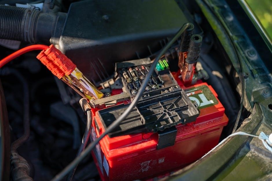
Proper battery maintenance ensures reliable performance. Check electrolyte levels monthly, adding distilled water as needed. Clean terminals with a wire brush to prevent corrosion; Charge the battery in a well-ventilated area, avoiding overcharging. Store the vehicle with the battery fully charged to prevent sulfation. Inspect cables for damage and secure connections. Use Club Car-approved charging systems for optimal care. Regular maintenance extends battery life and ensures consistent power delivery for your 2001 Gas Club Car.

Troubleshooting

This section guides you through identifying and resolving common issues. Use diagnostic tools to pinpoint problems and follow repair guidelines. Refer to the manual for detailed solutions and ensure safety by consulting professionals if needed.

5.1 Common Issues and Solutions

Common issues with the 2001 Gas Club Car include a failed accessory belt, which may shred and cause the cart to stop running. To resolve this, inspect the belt for wear and tear, and ensure proper alignment. Another issue is intermittent starting problems, often due to a worn ignition switch or loose battery connections. Check the ignition switch and tighten battery terminals. Additionally, difficulty in steering may occur from worn steering components or low tire pressure. Inspect the steering linkage and ensure tires are inflated to the recommended level. For sluggish performance, clean or replace the air filter and check spark plugs for fouling.

5.2 Diagnostic Techniques

Diagnosing issues with your 2001 Gas Club Car begins with a thorough inspection of key components. Check the accessory belt for wear or misalignment, as this can cause unexpected shutdowns. Inspect the ignition system, including the spark plugs and ignition switch, for any signs of wear or corrosion. Use a multimeter to test battery voltage and ensure connections are secure. Additionally, monitor the air filter for cleanliness, as a clogged filter can lead to poor engine performance. Always refer to the troubleshooting guide in this manual for specific diagnostic steps.

5.3 Repair Guidelines

When repairing your 2001 Gas Club Car, always use genuine parts to ensure compatibility and safety. Start by disconnecting the battery to prevent accidental start-ups. Refer to the torque specifications in the appendices for proper bolt tightening. Use appropriate tools to avoid damaging components. For complex repairs, consult the wiring diagrams or contact an authorized dealer. Regularly check and replace wear-and-tear items like air filters and spark plugs. Dispose of hazardous materials responsibly. If unsure, seek professional assistance to maintain your vehicle’s performance and longevity.

Parts and Accessories

This section provides guidance on identifying genuine parts, replacing wear-and-tear components, and installing accessories for your 2001 Gas Club Car. Ensure all parts are compatible with your model for optimal performance and safety.

6.1 Identifying Genuine Parts

Identifying genuine parts for your 2001 Gas Club Car is crucial for maintaining safety, performance, and warranty validity. Genuine parts are specifically designed to meet the vehicle’s specifications and ensure reliability. Always verify the part number against the official Club Car catalog or consult an authorized dealer to avoid counterfeit products. Look for the Club Car logo or “OEM” labeling to confirm authenticity. This ensures compatibility and adherence to safety standards, protecting your investment and ensuring optimal functionality.

6.2 Replacing Wear and Tear Components

Regularly inspect and replace wear and tear components on your 2001 Gas Club Car to maintain performance and prevent breakdowns. Items like brake pads, tires, and suspension parts may require replacement due to normal usage. Always use genuine Club Car parts for replacements to ensure compatibility and safety. Consult the maintenance schedule or contact an authorized dealer for guidance. Proper replacement of these components ensures your vehicle operates safely and efficiently, extending its lifespan and reliability.

6.3 Accessory Installation

When installing accessories on your 2001 Gas Club Car, ensure compatibility and safety by using genuine Club Car parts; Popular upgrades include lift kits, such as the RHOX 3 Drop Spindle Lift Kit, designed for Club Car DS models. Always follow the manufacturer’s instructions for installation to maintain vehicle performance and safety. Consult the owner’s manual or contact an authorized dealer for guidance on installing accessories like suspension upgrades or custom features. Proper installation ensures optimal functionality and longevity of your vehicle.

Storage and Transportation

Store your 2001 Gas Club Car in a dry, well-ventilated area, keeping the battery charged. For transportation, secure the vehicle on a trailer and ensure it is properly tied down. Always follow safety guidelines to prevent damage during transit and consult the manual for specific storage recommendations.

7.1 Proper Storage Conditions

Store your 2001 Gas Club Car in a dry, well-ventilated area to prevent moisture damage. Avoid direct sunlight and extreme temperatures. Ensure the vehicle is on a level surface and apply the parking brake. Keep the battery charged and terminals clean. If storing for extended periods, disconnect the battery and store it separately. Cover the vehicle to protect it from dust and debris. Ensure the fuel tank is full to prevent rust formation. Regularly inspect the storage area for any potential hazards or damage.

7.2 Transportation Safety Tips

When transporting your 2001 Gas Club Car, ensure it is securely fastened to a trailer or truck bed using heavy-duty straps. Always engage the parking brake and disable the ignition. Protect the vehicle from shifting during transit by properly securing all loose components. Regularly inspect the tie-down points and straps for wear or damage. Avoid sudden acceleration or braking while towing. Follow all local transportation regulations and ensure the vehicle is covered to prevent damage from debris. Proper transportation ensures safety and prevents potential damage to your Club Car.

7.3 Securing the Vehicle

To ensure your 2001 Gas Club Car remains safe and secure, always park it on a level surface and engage the parking brake. Disconnect the battery when storing for extended periods to prevent drain. Use a high-quality immobilizer or steering lock to deter theft. Cover the vehicle with a durable, weather-resistant cover to protect it from environmental damage. Regularly inspect the vehicle for signs of tampering or damage. Proper securing helps maintain your Club Car’s condition and prevents unauthorized use or vandalism.

Customization and Upgrades

Explore performance enhancements, aesthetic modifications, and upgrade considerations for your 2001 Gas Club Car to enhance functionality and personal style.

8.1 Performance Enhancements

Enhance your 2001 Gas Club Car’s performance with upgrades like lift kits and suspension modifications. The RHOX 3 Drop Spindle Lift Kit is compatible with Club Car DS models from 1982 to 2010, offering improved ground clearance and stability. Installation is straightforward, with components like A-Arms designed for easier handling. These upgrades not only boost performance but also maintain the vehicle’s longevity. Always ensure modifications align with the manufacturer’s guidelines to preserve safety and warranty validity.

8.2 Aesthetic Modifications

Personalize your 2001 Gas Club Car with aesthetic modifications to enhance its appearance. Popular upgrades include custom paint jobs, body kits, and decorative trim. Interior enhancements like premium seats, dashboard wraps, and LED lighting can also elevate the cart’s style. Always ensure modifications are compatible with the vehicle’s design and do not compromise safety or functionality. Consult the manual for guidance on maintaining the cart’s integrity while adding unique touches to make it stand out.

8.3 Upgrade Considerations

When considering upgrades for your 2001 Gas Club Car, ensure compatibility with the vehicle’s design and performance specifications. Consult the manual or authorized dealers to verify that modifications will not void the warranty or compromise safety. Prioritize upgrades that enhance functionality, such as suspension improvements or performance-enhancing kits. Avoid unauthorized modifications that could damage the vehicle or pose safety risks. Always test upgrades thoroughly to ensure proper integration and reliability.

Warranty and Support

Your 2001 Gas Club Car is backed by a comprehensive warranty. Contact authorized dealers for warranty inquiries or visit the official website for customer support and resources.

9.1 Understanding Your Warranty

Your 2001 Gas Club Car is covered by a limited warranty that protects against defects in materials and workmanship. The warranty period varies by component, with most parts covered for a specified time or mileage. It is essential to review the warranty terms in detail to understand what is included and what is excluded. Contact an authorized Club Car dealer for specific warranty inquiries or to verify coverage for your vehicle. Proper maintenance and adherence to guidelines can help ensure warranty validity.

9.2 Contacting Authorized Dealers

To ensure genuine parts and expert service, contact an authorized Club Car dealer. Visit the official Club Car website for a dealer locator tool. Provide your vehicle’s model and serial number for accurate assistance. Dealers offer maintenance, repairs, and genuine accessories, ensuring compliance with warranty terms. Contacting them directly guarantees reliable support and genuine components, maintaining your vehicle’s performance and safety standards. Always verify the dealer’s authorization to avoid unauthorized services.

9.3 Customer Support Channels

Club Car offers multiple customer support channels for assistance with your 2001 Gas Club Car. Reach out to their dedicated hotline or submit inquiries via email. Visit the official website for a comprehensive library of manuals, FAQs, and troubleshooting guides. Dealerships also provide direct support for parts and service. For additional help, join Club Car’s online community forums where owners and experts share tips and solutions. Ensure to have your vehicle’s serial number ready for faster assistance and personalized support.

Environmental Considerations

Adopt eco-friendly practices to minimize your 2001 Gas Club Car’s environmental impact. Regular maintenance reduces emissions, and proper disposal of hazardous materials ensures sustainability. Conserve resources responsibly.

10.1 Eco-Friendly Practices

To promote sustainability, adopt eco-friendly practices when operating your 2001 Gas Club Car. Consider converting to E85 fuel, which contains 85% ethanol, reducing greenhouse gas emissions. Regular maintenance ensures optimal performance and minimizes environmental impact. Always dispose of hazardous materials like batteries and fluids responsibly. Encourage sustainable driving habits, such as avoiding excessive idling and maintaining proper tire pressure. These practices help conserve resources and reduce your carbon footprint. Refer to your owner’s manual for detailed guidelines on environmentally responsible vehicle care.

10.2 Recycling Guidelines

Proper recycling is crucial for minimizing the environmental impact of your 2001 Gas Club Car. Always dispose of hazardous materials like batteries, fluids, and tires through authorized recycling centers. Check local regulations for guidelines on recycling automotive parts. Encourage the use of recycled components when replacing worn or damaged items. Participating in recycling programs helps reduce waste and conserve natural resources. For detailed instructions, consult your owner’s manual or contact an authorized Club Car dealer for assistance.

10.3 Reducing Emissions

To minimize the environmental impact of your 2001 Gas Club Car, regular maintenance is essential. Ensure proper tuning of the engine and exhaust system to reduce emissions. Always use the recommended grade of fuel and avoid overfilling the gas tank to prevent vapor emissions. Drive smoothly, avoiding rapid acceleration, and maintain a moderate speed. Keep the vehicle well-maintained, as a properly functioning engine emits fewer pollutants. Consider seasonal adjustments to optimize performance and emissions. By following these practices, you contribute to a cleaner environment while preserving your vehicle’s efficiency.

Appendices

This section provides additional resources, including torque specifications, wiring diagrams, and a glossary of terms, to support the maintenance and operation of your 2001 Gas Club Car.

11.1 Torque Specifications

Torque specifications are crucial for ensuring proper assembly and preventing damage to components. For the 2001 Gas Club Car, key bolt torque values include 30-40 ft-lbs for engine bolts and 50-60 ft-lbs for suspension components. Wheel lug nuts should be tightened to 80-90 ft-lbs in a star pattern. Always consult the manual or a certified mechanic for precise values, as incorrect torque can lead to mechanical failure. Refer to the detailed torque chart in this section for specific applications and guidelines.

11.2 Wiring Diagrams

The wiring diagrams section provides a detailed visual representation of the 2001 Gas Club Car’s electrical system. These diagrams illustrate the connections for components such as the ignition, headlights, and battery. Use these diagrams to identify circuits, troubleshoot electrical issues, or install aftermarket accessories. Always follow proper safety precautions when working with electrical systems. Refer to the legend for symbol explanations and ensure all connections are secure to avoid malfunctions. This guide is essential for DIY repairs and maintenance to keep your Club Car running smoothly.

11.3 Glossary of Terms

This section provides definitions for technical terms and components specific to the 2001 Gas Club Car. Terms like “Throttle,” “Differential,” and “Battery” are explained to help owners understand the vehicle’s mechanics. The glossary includes abbreviations and industry-specific jargon, ensuring clarity for maintenance and troubleshooting. Familiarizing yourself with these terms will enhance your ability to follow instructions and communicate effectively with service professionals. This reference guide is essential for all owners to navigate the technical aspects of their Club Car confidently.

Contact Information

This section defines key terms related to the 2001 Gas Club Car, such as “Throttle,” “Differential,” and “Battery.” These definitions help owners understand technical components and industry-specific language. Terms are explained clearly to aid in maintenance and troubleshooting. The glossary ensures owners can communicate effectively with service professionals and follow manual instructions confidently. It serves as a quick reference for understanding the vehicle’s mechanics and terminology.

12.1 Authorized Dealers

For genuine parts, service, and support, contact your local authorized Club Car dealer. Dealers provide expert advice, maintenance, and repairs, ensuring your 2001 Gas Club Car operates safely and efficiently. They offer original equipment manufacturer (OEM) parts and accessories, guaranteed to meet quality standards. Authorized dealers also handle warranty claims and provide detailed guidance on vehicle customization and upgrades. Visit the official Club Car website or call the customer support hotline to locate your nearest authorized dealer. They are your trusted partners for all your golf cart needs.

12.2 Customer Support Hotline

The Club Car customer support hotline is available 24/7 to assist with troubleshooting, maintenance, and warranty inquiries. Call toll-free to speak with knowledgeable representatives who can address concerns about your 2001 Gas Club Car. They provide guidance on repairs, parts compatibility, and operational best practices. Whether you need immediate assistance or general advice, the hotline is your direct link to expert support. For multilingual assistance, select the appropriate option during the call. This service ensures your vehicle runs smoothly and safely, backed by Club Car’s commitment to customer satisfaction.

12.3 Official Website

Visit the Club Car official website for comprehensive resources, including downloadable owner’s manuals, parts catalogs, and troubleshooting guides. The site offers detailed information on the 2001 Gas Club Car, along with maintenance tips and warranty details. You can also explore accessories, request support, and find authorized dealers. The website provides a user-friendly interface to navigate through product information, ensuring you have all the tools needed to maintain and enhance your vehicle. Regular updates and promotions are also available for registered users.

Continue Reading

canon 60d instruction manual

Welcome to the Canon EOS 60D instruction manual‚ your comprehensive guide to mastering this powerful DSLR camera. Discover its features‚ shooting modes‚ and customization options to unlock your full creative potential.

1.1 Overview of the Canon EOS 60D

The Canon EOS 60D is a high-performance DSLR camera designed for enthusiasts and professionals. It features an 18 MP CMOS sensor‚ DIGIC 4 processor‚ and advanced modes for stills and video. With its robust build‚ intuitive controls‚ and versatile features‚ it offers exceptional image quality and creative flexibility for photographers of all levels.

1.2 Importance of the Instruction Manual

The Canon EOS 60D instruction manual is essential for understanding and maximizing the camera’s capabilities. It provides detailed guidance on setup‚ shooting modes‚ and advanced features‚ ensuring users can troubleshoot issues and optimize their photography skills. This comprehensive guide is a must-have for both beginners and experienced photographers to unlock the camera’s full potential effectively.

Technical Specifications of the Canon EOS 60D

The Canon EOS 60D features an 18MP APS-C CMOS sensor‚ DIGIC 4 processor‚ ISO range of 100-6400‚ and 5.3 fps continuous shooting‚ ensuring high-quality images and performance.

2.1 Sensor and Processor Details

The Canon EOS 60D is equipped with an 18.0 megapixel APS-C CMOS sensor‚ delivering sharp‚ detailed images. Paired with the DIGIC 4 image processor‚ it ensures enhanced color accuracy‚ reduced noise‚ and improved processing speed for optimal performance.

2.2 ISO Range and Noise Performance

The EOS 60D offers an ISO range of 100-6400‚ expandable to 12800. It delivers excellent noise performance‚ capturing clear images in low-light conditions. The DIGIC 4 processor minimizes grain‚ ensuring high-quality photos even at higher ISO settings.

2.3 Continuous Shooting and Frame Rates

The EOS 60D supports continuous shooting at up to 5.3 frames per second‚ ideal for capturing dynamic action or wildlife. It can shoot up to 16 RAW images or 58 JPEGs in a single burst‚ making it suitable for fast-paced photography sessions.

Camera Design and Build Quality

The EOS 60D features a sturdy‚ lightweight design with dimensions of 144.5 x 105.8 x 78.6 mm and a weight of 755 grams‚ ensuring comfort during extended use.

3.1 Dimensions and Weight

The Canon EOS 60D measures 144.5 mm in width‚ 105.8 mm in height‚ and 78.6 mm in depth‚ with a lightweight body weighing approximately 755 grams. Its compact and balanced design ensures portability and comfort during extended photography sessions.

3.2 LCD Screen and Viewfinder

The Canon EOS 60D features a 3-inch vari-angle LCD screen with 1‚040‚000 dots for clear image playback and menu navigation. The optical viewfinder provides 96% coverage and 0.95x magnification‚ ensuring precise framing and focus control for enhanced shooting precision and comfort.

3.4 Weather Sealing and Durability

The Canon EOS 60D features a robust magnesium alloy body for enhanced durability. It includes weather sealing to protect against dust and moisture‚ ensuring reliable performance in challenging conditions. However‚ it is not fully weatherproof‚ so extra care is recommended in harsh environments. Regular maintenance and proper storage are advised to extend its lifespan.

Operating Modes and Shooting Options

The Canon EOS 60D offers versatile shooting modes‚ including Manual (M)‚ Aperture Priority (Av)‚ Shutter Priority (Tv)‚ and Program (P)‚ catering to both beginners and advanced photographers.

4.1 Manual Mode (M)

In Manual (M) mode‚ you gain full control over aperture and shutter speed‚ allowing for precise adjustments to achieve your desired creative effect. Use the Main Dial to adjust shutter speed and the Quick Control Dial for aperture settings. This mode is ideal for experienced photographers seeking maximum flexibility.

Access Manual mode via the Mode Dial. Adjustments are confirmed on the LCD screen‚ ensuring accurate control. Fine-tune exposure using the ISO button and exposure compensation (+/-5 stops). Manual mode offers unparalleled creative freedom‚ making it perfect for experimenting with lighting and composition.

4.2 Aperture Priority Mode (Av)

In Aperture Priority mode‚ you set the aperture‚ and the camera automatically adjusts the shutter speed. This mode is ideal for controlling depth of field‚ ensuring sharp focus on subjects while blurring backgrounds. Adjust the aperture using the Quick Control Dial‚ and view the selected aperture on the LCD screen.

The EOS 60D allows aperture settings from f/1.4 to f/32‚ depending on the lens. This mode is perfect for portrait photography‚ where subject isolation is key. The camera ensures optimal exposure by automatically selecting the appropriate shutter speed for your chosen aperture.

4.3 Shutter Priority Mode (Tv)

In Shutter Priority mode‚ you control the shutter speed‚ and the camera adjusts the aperture. This mode is ideal for capturing motion‚ such as freezing fast-moving subjects or creating artistic motion blur. Select the shutter speed using the Main Dial‚ and the EOS 60D automatically selects the appropriate aperture for optimal exposure.

Shutter speeds range from 1/8000th of a second to 30 seconds‚ offering flexibility for various lighting conditions. Use faster speeds for sports and slower speeds for creative effects like flowing water or light trails‚ ensuring dynamic and visually appealing results every time.

4.4 Program Mode (P)

Program Mode (P) offers a balance between simplicity and flexibility. The camera automatically sets both aperture and shutter speed for optimal exposure‚ ideal for everyday shooting. This mode is perfect for beginners or those who want ease of use while still achieving great results.

While the camera handles most settings‚ you can still customize options like exposure compensation and Auto ISO‚ allowing for some creative control without manual adjustments. Program Mode is a versatile choice for capturing sharp‚ well-exposed images in various lighting conditions.

Autofocus and Metering Systems

This section explains the Canon EOS 60D’s advanced autofocus and metering systems‚ designed to enhance accuracy and control in various shooting conditions.

5.1 9-Point Autofocus System

The Canon EOS 60D features a high-precision 9-point autofocus system‚ ensuring quick and accurate subject tracking. Each AF point is cross-type for enhanced performance under various lighting conditions‚ providing reliable focusing even in challenging environments.

5.2 Metering Modes (Evaluative‚ Center-Weighted‚ Spot)

The Canon EOS 60D offers three metering modes: Evaluative‚ Center-Weighted‚ and Spot. Evaluative metering analyzes the entire scene for balanced exposure. Center-Weighted prioritizes the center for subject-focused lighting. Spot metering measures a specific area‚ ideal for precise control in challenging lighting conditions‚ ensuring accurate exposure for your desired subject.

Image and Video Capabilities

The Canon EOS 60D captures stunning 18MP still images in RAW and JPEG formats and records Full HD video at 30fps‚ ensuring sharp details and vibrant colors.

6.1 Still Image Formats (RAW‚ JPEG)

The Canon EOS 60D supports RAW and JPEG formats‚ offering flexibility for photographers. RAW files capture uncompressed data for advanced editing‚ while JPEG files are processed in-camera for smaller sizes. The camera allows simultaneous RAW+JPEG shooting‚ enabling quick sharing and high-quality post-processing‚ catering to both professionals and casual shooters.

6.2 Video Recording Features

The Canon EOS 60D captures Full HD video at 1920×1080 pixels with frame rates of 30‚ 25‚ or 24 fps. It supports manual controls for aperture‚ shutter speed‚ and ISO during recording. Movie Servo AF enables continuous autofocus‚ and an external microphone jack enhances audio quality‚ making it ideal for both casual and professional videography needs.

6.3 Image Resizing and Cropping

The Canon EOS 60D allows resizing images directly in the camera without a computer. It supports various JPEG sizes‚ including Large‚ Medium‚ and Small options. Additionally‚ the camera features in-camera cropping‚ enabling precise adjustments to image compositions for tailored results‚ enhancing workflow efficiency for photographers.

Customization and Personalization

The Canon EOS 60D offers extensive customization options‚ allowing photographers to tailor camera settings to their preferences. Users can personalize controls‚ create custom shooting modes‚ and organize frequently used settings for enhanced efficiency in their workflow.

7.1 Custom Shooting Modes (C1‚ C2‚ C3)

The Canon EOS 60D’s C1‚ C2‚ and C3 modes allow photographers to save customized settings for quick access‚ enhancing workflow efficiency. These modes enable users to tailor camera configurations to specific shooting scenarios‚ ensuring optimal results without repeated adjustments.

7.2 My Menu Setup

The My Menu feature on the Canon EOS 60D allows users to create a personalized menu of frequently used settings. Accessible via the camera’s menu system‚ it streamlines workflow by providing quick access to customized options‚ enhancing efficiency during photo shoots.

7.3 Customizing Buttons and Controls

The Canon EOS 60D allows users to customize buttons and controls to suit their preferences. The Quick Control Dial and Main Dial can be programmed for specific functions‚ enabling faster access to settings like ISO and shutter speed. This feature enhances personal workflow and shooting efficiency.

Accessories and Compatible Equipment

The Canon EOS 60D supports a range of accessories‚ including Speedlite flashes‚ EF-S lenses‚ and remote controls‚ enhancing functionality and shooting versatility for photographers.

8.1 Canon Speedlite Flash Compatibility

The Canon EOS 60D is compatible with various Speedlite flashes‚ including the 580EX II and 430EX III-RT‚ offering advanced lighting control and wireless functionality. These flashes enhance creativity and provide precise illumination for diverse shooting scenarios‚ ensuring professional-grade results. Refer to the manual or Canon’s official support page for a full list of compatible models and setup instructions.

8.2 EF-S Lens Compatibility

The Canon EOS 60D supports EF-S lenses‚ designed for APS-C sensors‚ offering a compact and lightweight design while maintaining high optical quality. These lenses are optimized for the 60D’s sensor size‚ ensuring enhanced performance and image quality. While EF lenses are also compatible‚ EF-S lenses provide a more tailored experience for this camera model.

8.3 Remote Control and Wireless Accessories

The Canon EOS 60D supports remote control via infrared or wireless accessories‚ enhancing shooting convenience. Use the optional Remote Controller RC-6 for wireless shutter release‚ or the EOS Utility via USB for advanced control. Additionally‚ third-party apps and devices can enable remote operation‚ offering greater flexibility and creativity in your photography workflow.

Troubleshooting and Maintenance

Troubleshoot common issues like error messages and sensor cleaning. Regular maintenance ensures optimal performance‚ including cleaning the lens and sensor‚ and managing battery life effectively for long-term reliability.

9.1 Common Error Messages and Solutions

Address error messages like “Card Error” by formatting or replacing the memory card. For lens issues‚ ensure proper attachment or clean contacts. If problems persist‚ reset the camera or update firmware. Regularly clean the sensor and lens to prevent dust-related errors and ensure optimal image quality. Refer to the manual for detailed solutions.

9.2 Cleaning the Sensor and Lens

Regularly clean the sensor and lens to maintain image quality. Use a soft‚ dry cloth for the lens and a blower or swabs for the sensor. Enable the camera’s cleaning mode to open the shutter. Avoid harsh chemicals and ensure the camera is off during cleaning. For stubborn spots‚ consider professional service.

9.3 Battery and Power Management

For optimal performance‚ charge the LP-E6 battery fully before use. Avoid over-discharging‚ as it may reduce battery life. Use the camera’s power-saving features‚ such as auto-shutoff‚ to conserve energy. Replace batteries when the level indicator shows low power. Store spare batteries in a cool‚ dry place to maintain longevity.

Always use genuine Canon batteries for reliable performance and to prevent damage to your camera.

Downloading and Navigating the Instruction Manual

Visit Canon’s official website or trusted sources like Manuals.co.uk to download the EOS 60D manual in PDF format. Use the search bar to find and navigate the document easily;

10.1 Where to Download the Manual

The Canon EOS 60D manual is available for free on Canon’s official website and trusted platforms like Manuals.co.uk. Simply search for “Canon EOS 60D manual” and download the PDF file to access detailed instructions and guidelines for your camera.

10.2 Navigating the Manual’s Content

The Canon EOS 60D manual is a comprehensive guide organized into clear sections. Use the table of contents or index to quickly locate specific topics. Symbols and references throughout the manual help you understand key features‚ precautions‚ and advanced functions‚ ensuring easy navigation and efficient learning of your camera’s capabilities.

10.3 Printing and Saving the Manual

The Canon EOS 60D manual is available as a PDF file‚ allowing easy printing and saving. Download the file‚ save it to your device‚ and print specific sections or the entire manual for reference. Use the PDF viewer’s tools to navigate and print only the pages you need‚ ensuring convenient access to essential information whenever required.

Master your Canon EOS 60D with this comprehensive guide. Explore its features‚ customize settings‚ and practice regularly to enhance your photography skills. Refer to the manual for future guidance and troubleshooting.

11.1 Summary of Key Features

The Canon EOS 60D offers an 18MP CMOS sensor‚ DIGIC 4 processor‚ ISO 100-6400‚ and full HD video recording. It features a vari-angle LCD‚ 9-point AF system‚ and various shooting modes‚ including manual‚ aperture priority‚ and shutter priority. Customizable settings and compatibility with EF-S lenses enhance its versatility for photographers.

11.2 Encouragement to Explore and Practice

Embrace the Canon EOS 60D’s capabilities by experimenting with different modes and techniques. Practice regularly to refine your skills‚ from mastering manual focus to capturing stunning videos. Exploration and consistent practice will help you unlock the camera’s full potential and elevate your photography to new heights creatively.

Continue Reading

hp service manual

HP Service Manuals are comprehensive guides providing detailed instructions for maintaining, troubleshooting, and repairing HP devices. They cover laptops, printers, plotters, and more, ensuring optimal performance and longevity.

Overview of HP Service Manuals

HP Service Manuals are detailed technical documents designed to assist users and technicians in maintaining, troubleshooting, and repairing HP devices. These manuals cover a wide range of products, including laptops, printers, plotters, and more. They provide step-by-step instructions, diagrams, and parts lists to ensure proper servicing. Whether for routine maintenance or complex repairs, HP Service Manuals are essential resources for extending device lifespan and resolving issues efficiently. They are available for various models and can be accessed through official HP channels or authorized providers.

Importance of Service Manuals for HP Devices

HP Service Manuals are crucial for ensuring proper maintenance, troubleshooting, and repair of HP devices. They provide detailed instructions, diagrams, and guidelines for users and technicians, enabling efficient issue resolution. These manuals help prevent costly damages by outlining correct procedures, ensuring safety, and maintaining warranty compliance. By following service manuals, users can extend device lifespan, optimize performance, and resolve problems without professional intervention. Accessing official HP Service Manuals is essential for adhering to manufacturer guidelines and ensuring reliable device operation.

Types of HP Service Manuals

HP Service Manuals cater to various devices, including laptops, printers, and plotters, providing specific repair and maintenance guidance for each product category.

HP Laptop Service Manuals

HP Laptop Service Manuals provide detailed guidance for maintaining and repairing HP laptops, including models like Pavilion, Compaq, and ProBook. These manuals cover diagnostic tools, troubleshooting steps, and repair procedures for hardware components such as motherboards, screens, and keyboards. They also include instructions for upgrading RAM, replacing batteries, and servicing cooling systems. Advanced sections focus on BIOS updates and system recovery. These resources are essential for extending the lifespan of HP laptops and ensuring optimal performance. Users can download these manuals from HP’s official support website or authorized service providers.

HP Printer Service Manuals

HP Printer Service Manuals are essential resources for diagnosing and resolving issues with HP printers. These manuals offer detailed repair procedures, troubleshooting guides, and maintenance tips. They cover various models, including LaserJet and DeskJet series, providing step-by-step instructions for replacing parts like toner cartridges, printheads, and fuser kits. Additionally, they include error code explanations and solutions to common printing problems. Users can download these manuals from HP’s official support website or authorized service providers to ensure proper servicing and extend printer lifespan.

HP Plotter Service Manuals

HP Plotter Service Manuals provide in-depth guidance for maintaining and repairing HP plotters, ensuring optimal performance. These manuals cover models like DesignJet T120 and T520, offering repair procedures, parts replacement, and troubleshooting tips. They address common issues such as printhead alignment and paper feed problems. Available for download from HP’s support website or authorized providers, these manuals help users resolve technical difficulties efficiently, extending the lifespan of their HP plotters and maintaining high-quality output.

How to Download HP Service Manuals

HP Service Manuals can be downloaded from the official HP Support website, authorized service providers, or third-party resources, ensuring easy access to maintenance and repair guides.

Official HP Support Website

The official HP Support website is the primary source for downloading genuine service manuals. Visit support.hp;com, search for your device model, and access the service manual section. This platform offers free, reliable, and updated guides for various HP products, including printers, laptops, and plotters. For example, manuals for HP LaserJet M9040 or HP DesignJet T120 are readily available. The website ensures authenticity and compliance with HP’s standards, making it the most trusted resource for users.

Authorized Service Providers

Authorized Service Providers (ASPs) are certified by HP to offer genuine service manuals and repair services. These providers ensure compliance with HP standards, minimizing risks of warranty voidance or device damage. Users can locate ASPs through HP’s official support website, ensuring access to authentic and updated manuals. For instance, ASPs provide manuals for models like HP LaserJet M9040 or DesignJet T120, maintaining device performance and longevity. Using ASPs guarantees reliability and adherence to HP’s quality assurance protocols.

Third-Party Resources

Third-party websites like ManualsLib and ManualsDir offer free downloads of HP service manuals for various devices, including laptops, printers, and plotters. While these resources provide convenient access, they may not always be updated or authenticated by HP. Users should exercise caution, as incorrect or outdated information can lead to improper repairs or warranty voidance. Always verify the source and cross-check with HP’s official support for accuracy and compliance with safety standards.

Maintenance and Repair Procedures

HP Service Manuals provide detailed maintenance schedules and repair procedures for devices like LaserJet printers and Designjet plotters, ensuring optimal performance and extending product lifespan.

Common Maintenance Tasks

Regular maintenance tasks for HP devices include cleaning printer heads, updating firmware, and replacing worn parts. Service manuals guide users through these processes to ensure optimal performance. For laptops, tasks like cooling system checks and battery calibration are essential. Printers require ink cartridge replacements and paper tray alignments. Plotters may need printhead cleaning and media alignment adjustments. Following these routines helps prevent issues and extends device lifespan. Proper maintenance ensures reliability and efficiency, as outlined in HP service manuals.

Advanced Repair Techniques

Advanced repair techniques for HP devices involve complex diagnostic procedures and component replacements. Service manuals detail methods for diagnosing hardware issues, such as motherboard failures or printhead malfunctions. Techniques include soldering, circuit board repairs, and firmware updates. For printers, advanced tasks may involve replacing fuser assemblies or imaging units. Laptops might require screen replacements or logic board repairs. These procedures demand precision and specialized tools, as outlined in HP service manuals to ensure repairs are done safely and effectively.

Troubleshooting Guides

Troubleshooting Guides in HP Service Manuals provide step-by-step solutions for diagnosing and resolving common issues. They include error code interpretations, diagnostic tools, and repair procedures for various HP devices.

Diagnosing Common Issues

HP Service Manuals provide detailed diagnostic tools and procedures for identifying common issues in devices. Users can troubleshoot error codes, perform system checks, and isolate hardware or software faults. The manuals offer step-by-step guides for resolving issues like printer errors, laptop boot problems, or plotter connectivity issues. By following these diagnostic steps, users can pinpoint the root cause and apply the appropriate repair or maintenance solution, ensuring optimal device performance and extending lifespan. Regular diagnostics help prevent potential failures and maintain efficiency across HP products.

Step-by-Step Troubleshooting

HP Service Manuals offer systematic troubleshooting guides to resolve device issues efficiently. Users can identify symptoms, consult error codes, and follow detailed repair procedures. Manuals provide diagnostic tools and step-by-step instructions for tasks like verifying connections, updating firmware, or replacing components. Advanced sections include specialized diagnostic software and hardware tests. These guides empower users to address common and complex problems, minimizing downtime and ensuring optimal performance. Regular use of these resources enhances troubleshooting skills and maintains device reliability effectively.

Authorized Service Providers

HP Authorized Service Providers are HP’s recommended solution for expert repairs, using genuine parts and adhering to safety standards, ensuring repairs are warranty compliant.

Benefits of Using Authorized Services

Authorized Service Providers offer expert repairs using genuine HP parts, ensuring devices function optimally. They provide warranty compliance, reducing risks of voiding coverage. Their technicians are HP-trained, guaranteeing high-quality service and safe repairs. Using ASPs ensures adherence to HP standards, maintaining device performance and longevity. This service is recommended for complex repairs, providing peace of mind and reliable outcomes for HP users seeking professional assistance.

Locating an ASP

To locate an Authorized Service Provider (ASP), visit HP’s official support website at https://support.hp.com/. Enter your product details to find nearby authorized service centers. You can also use the HP Service Center Locator tool for precise results. Contacting HP customer support directly can provide additional guidance. Ensure to verify the ASP’s certification to guarantee genuine parts and warranty-compliant repairs, maintaining your device’s performance and validity of its warranty coverage effectively.

Warranty and Legal Considerations

Adhering to HP’s guidelines ensures warranty validity. Unauthorized repairs or parts may void your warranty. Always use HP-approved services to maintain compliance and avoid legal issues.

Warranty Voidance Risks

Modifying or repairing HP devices without authorization can void your warranty. Unauthorized parts or services may damage your device and lead to legal consequences. Always use HP-approved services to avoid risks and ensure compliance with warranty terms. Non-compliant actions can result in denied support and financial losses. Adhere to HP guidelines to maintain your device’s integrity and warranty coverage. Unauthorized repairs are strictly prohibited and may void your warranty immediately.

Compliance with HP Policies

Compliance with HP policies ensures adherence to safety, legal, and performance standards. Using genuine HP parts and authorized services maintains device integrity. Unauthorized modifications or repairs may lead to penalties or support denial. HP policies protect consumers by ensuring reliability and security. Following guidelines guarantees proper functionality and warranty validity. Non-compliance risks legal action and voids support entitlements. Always use HP-approved resources for repairs and maintenance to stay compliant and avoid penalties.

HP Service Manuals are essential resources for maintaining, troubleshooting, and repairing devices. They ensure optimal performance, longevity, and compliance with HP policies, benefiting both professionals and DIY users.

Final Thoughts on HP Service Manuals

HP Service Manuals are indispensable for professionals and DIY enthusiasts, offering detailed guidance for maintenance, troubleshooting, and repairs. They ensure devices operate efficiently and prolong their lifespan. With HP shifting towards official channels for manual distribution, users must rely on authorized sources to access authentic documentation. Adhering to these manuals helps avoid warranty voidance and ensures compliance with HP policies, making them a vital resource for anyone working with HP devices.

Continue Reading

honda accord repair manual pdf

The Honda Accord Repair Manual PDF is a comprehensive guide for maintaining and repairing Honda Accord models from 1990 to 2015. It provides detailed instructions, diagrams, and charts to help users diagnose and fix issues. Whether you’re a DIY enthusiast or a professional mechanic, this manual offers essential information to ensure safety and proper repair techniques. It covers various aspects, including engine, transmission, electrical systems, and more, making it an invaluable resource for troubleshooting and maintaining your Honda Accord effectively.

By following the manual, users can perform routine maintenance, identify common problems, and repair complex components. It emphasizes safety and proper tools, ensuring repairs are done efficiently and correctly. This resource is a must-have for anyone looking to keep their Honda Accord in optimal condition, saving time and money on repairs. With its clear instructions and detailed illustrations, the Honda Accord Repair Manual PDF empowers users to take control of their vehicle’s maintenance and repairs with confidence.

Overview of the Honda Accord Models Covered in the Manual

The Honda Accord Repair Manual PDF covers a wide range of models, including the 1990-1993, 1994-1997, 2001, 2008-2010, and 2011-2012 editions. It also includes specific guides for the V6 models and detailed instructions for the 2015 Accord. The manual is comprehensive, ensuring compatibility with various engine types, such as the L4-2.4L, and transmission systems. Whether you own an older or newer Honda Accord, this manual provides detailed repair and maintenance information tailored to your vehicle’s needs.

  • 1990-1993 models
  • 1994-1997 models
  • 2001 model
  • 2008-2010 models
  • 2011-2012 models
  • 2015 model

This extensive coverage makes it an essential resource for DIY enthusiasts and professionals alike, ensuring accurate and effective repairs across all included Accord generations.

Importance of Using a Repair Manual for DIY Maintenance and Repairs

A repair manual is essential for DIY maintenance and repairs, providing clear instructions, diagrams, and safety guidelines. It helps users understand complex procedures, ensuring repairs are done correctly and safely. By following the manual, DIYers can avoid costly mistakes and ensure their Honda Accord runs efficiently. It also helps identify the right tools and parts needed, saving time and money. With a repair manual, individuals can confidently tackle repairs, knowing they have accurate guidance tailored to their vehicle.

Using a repair manual empowers car owners to maintain their vehicles independently, reducing reliance on professional mechanics. It fosters a deeper understanding of the car’s systems, enabling better troubleshooting and problem-solving. Regular maintenance and timely repairs can extend the lifespan of the Honda Accord, improving performance and reliability. A repair manual is a valuable resource for anyone aiming to keep their vehicle in optimal condition without incurring high costs.

Honda Accord Repair Manual PDF: Content and Structure

The Honda Accord Repair Manual PDF is organized into sections covering engine, transmission, electrical systems, and more. It includes detailed diagrams, step-by-step instructions, and troubleshooting guides. The manual is structured to help users easily navigate and locate specific repair information, ensuring efficient and effective maintenance. Its clear layout and comprehensive content make it an essential tool for both novice and experienced mechanics working on Honda Accord models.

Sections Included in the Manual (Engine, Transmission, Electrical Systems, etc.)

The Honda Accord Repair Manual PDF includes detailed sections on engine repair, transmission maintenance, electrical systems, braking systems, suspension, and body repairs. It also covers fuel injection, cooling systems, exhaust systems, and steering mechanisms. Each section provides diagnostic procedures, repair instructions, and torque specifications. The manual includes wiring diagrams, fuse layouts, and troubleshooting guides for electrical issues. Additionally, it covers routine maintenance schedules, lubrication charts, and specifications for various components. This comprehensive structure ensures all aspects of the vehicle are thoroughly addressed, making it an indispensable resource for both DIY enthusiasts and professional mechanics.

Navigating the Manual: How to Find Specific Repair Information

The Honda Accord Repair Manual PDF is organized for easy navigation, featuring a detailed index and table of contents. Users can quickly locate specific repair information by searching keywords or browsing through categorized sections. The manual includes cross-references, diagrams, and charts to guide users through complex procedures. Each section is clearly labeled, with step-by-step instructions and visual aids to ensure clarity. This structured approach allows users to efficiently find and apply the necessary repair information, saving time and reducing confusion.

Engine Repair and Maintenance

The Honda Accord Repair Manual PDF provides a comprehensive guide for engine repair and maintenance, covering common issues, diagnostic steps, and detailed repair procedures for optimal performance and longevity.

Common Engine Issues in Honda Accord Models

Common engine issues in Honda Accord models include oil leaks, faulty oxygen sensors, and problems with the VTEC system in V6 engines. Older models may experience excessive oil consumption and cylinder head issues. The manual details these problems, providing step-by-step solutions and preventive measures to ensure optimal engine performance and longevity. It also covers troubleshooting techniques for misfires, coolant leaks, and timing belt failures, helping users address these issues effectively.

  • Oil Leaks: Often caused by worn engine gaskets or seals.
  • Faulty Oxygen Sensors: Can lead to poor fuel efficiency and performance.
  • VTEC System Issues: Common in V6 models, requiring specialized tools for repair.

By addressing these issues early, Accord owners can prevent costly repairs and maintain their vehicle’s reliability.

Step-by-Step Guide to Replacing Engine Components

Replacing engine components in your Honda Accord requires careful planning and adherence to the manual’s instructions. Start by gathering tools like a torque wrench, socket set, and new components. Disconnect the battery and drain fluids to ensure safety. Follow the manual’s step-by-step guide to remove the old part, install the new one, and reconnect components. Tighten bolts to specified torque values and test the system for proper function. Always refer to the manual for specific instructions tailored to your Accord model.

  • Tools Needed: Torque wrench, socket set, and replacement parts.
  • Precautions: Disconnect the battery and drain fluids before starting.
  • Key Steps: Remove old component, install new part, and reconnect systems.
  • Final Check: Test functionality and ensure all connections are secure.

By following these steps, you can replace engine components effectively, ensuring your Accord runs smoothly and efficiently.

Transmission and Drivetrain

The Honda Accord Repair Manual PDF provides comprehensive coverage of transmission and drivetrain components, ensuring proper maintenance and repair for smooth operation across all models.

Understanding Transmission Problems in Honda Accord

Transmission issues in Honda Accord models often stem from fluid leaks, worn clutch packs, or faulty sensors. Slipping gears, delayed engagement, and unusual noises are common symptoms. The manual details how to identify these problems through diagnostic troubleshooting. It explains how to check transmission fluid levels, inspect for leaks, and interpret error codes. Understanding these issues early helps prevent major repairs. Regular maintenance, such as fluid changes, can extend transmission life. The manual provides step-by-step guidance for diagnosing and addressing these concerns effectively.

DIY Transmission Repair: Tips and Precautions

When tackling DIY transmission repairs, use the correct tools and follow the manual’s torque specifications to avoid damaging components. Clean the work area to prevent contamination. Replace worn or damaged parts with genuine Honda components for reliability. Always drain and refill transmission fluid after repairs. If unsure, consult a professional to avoid costly mistakes. The manual provides detailed steps to ensure safety and accuracy during repairs, helping you restore your Honda Accord’s transmission to optimal performance.

Electrical Systems and Wiring

The Honda Accord Repair Manual PDF provides detailed insights into electrical systems, including circuit diagrams and troubleshooting guides. It covers diagnostics, wiring repairs, and component replacements, ensuring users can identify and resolve electrical issues efficiently. The manual emphasizes proper tools and safety practices to prevent damage or injury, making it a reliable resource for both professional mechanics and DIY enthusiasts.

Diagnosing Electrical Faults Using the Manual

The Honda Accord Repair Manual PDF offers detailed guidance for diagnosing electrical faults, including circuit diagrams and fault code interpretations. It provides step-by-step procedures for identifying issues in wiring, fuses, and sensors. Users can locate specific fault codes and understand their meanings, enabling precise troubleshooting. The manual also includes tools and methods for testing electrical components, such as using a multimeter to check voltage and resistance. By following these guidelines, users can pinpoint and resolve electrical problems efficiently and safely.

With clear instructions and visual aids, the manual simplifies complex diagnostics, ensuring users can address issues confidently. It emphasizes proper safety practices to avoid further damage or injury, making it an essential resource for electrical system maintenance and repair.

Repairing Faulty Wiring and Fuses

The Honda Accord Repair Manual PDF provides clear instructions for repairing faulty wiring and fuses. It outlines the necessary tools, such as wire strippers and multimeters, to diagnose and fix electrical issues. Step-by-step guides help users locate and replace damaged wires, repair connectors, and identify blown fuses. The manual emphasizes safety practices, such as disconnecting the battery before starting work. Detailed diagrams and charts ensure precise repairs, helping users restore their vehicle’s electrical system to optimal functionality efficiently and safely.

By following the manual’s guidance, users can address wiring and fuse problems confidently, preventing further damage and ensuring reliable operation of their Honda Accord’s electrical components. The comprehensive instructions make it easier to tackle even complex repairs with accuracy and confidence.

Maintenance Schedule and Routine Care

The Honda Accord Repair Manual PDF outlines a detailed maintenance schedule, ensuring optimal performance and longevity. It provides guidelines for regular inspections, fluid changes, and part replacements, tailored to different mileage intervals. By following the recommended routine, owners can prevent potential issues and keep their vehicle in prime condition, reducing the need for costly repairs and extending the lifespan of their Honda Accord.

Recommended Maintenance Intervals for Honda Accord

The Honda Accord Repair Manual PDF provides specific maintenance intervals to ensure optimal vehicle performance. Oil changes are recommended every 5,000 to 7,500 miles, while tire rotations should occur every 6,000 to 8,000 miles. Spark plug replacements are typically needed at 30,000 to 100,000 miles, depending on the model year. The manual also outlines intervals for fluid checks, air filter replacements, and belt inspections. Following these schedules helps prevent potential issues and ensures the longevity and reliability of your Honda Accord.

  • Oil changes: 5,000–7,500 miles
  • Tire rotations: 6,000–8,000 miles
  • Spark plugs: 30,000–100,000 miles
  • Fluid checks: Every 3,000–5,000 miles
  • Air filter: Every 15,000–30,000 miles
  • Belt inspections: At 50,000 and 90,000 miles

Adhering to these intervals ensures your Honda Accord runs smoothly and maintains its performance over time. The manual serves as a valuable resource for DIY maintenance, helping you keep your vehicle in peak condition.

Essential Tools and Supplies for Regular Maintenance

Regular maintenance for your Honda Accord requires specific tools and supplies to ensure tasks are performed safely and effectively. A socket set, wrenches, screwdrivers, and pliers are essential for most repairs. Additional items include an oil drain pan, funnel, and new oil filters. Tire pressure gauges and wheel chocks are crucial for tire rotations and inspections. A torque wrench is necessary for precise bolt tightening. Rags, safety glasses, and gloves are also recommended to protect yourself and keep your workspace clean. Having these tools on hand ensures maintenance is efficient and safe.

  • Socket set and wrenches
  • Screwdrivers and pliers
  • Oil drain pan and funnel
  • Tire pressure gauge
  • Torque wrench
  • Rags, gloves, and safety glasses

Common Repair Issues and Solutions

The Honda Accord often experiences issues like faulty oxygen sensors, transmission slipping, and worn brake pads. Replacing these components promptly can prevent further damage and costly repairs.

  • Oxygen sensor replacement
  • Transmission fluid flush
  • Brake pad replacement

Frequently Encountered Problems in Honda Accord Models

Honda Accord models often experience issues such as faulty oxygen sensors, transmission slipping, and worn brake pads. Additionally, problems with the VTC actuator, faulty alternators, and electrical system malfunctions are common. Many owners report issues with the cooling system, including radiator leaks and failed water pumps. Transmission problems, especially in older models, can lead to slipping or hesitation. These issues are well-documented in repair manuals, allowing owners to diagnose and address them effectively. Regular maintenance can help prevent these common problems from escalating.

Cheap and Effective Fixes for Common Issues

For common Honda Accord issues like faulty oxygen sensors or transmission problems, consider cost-effective solutions. Cleaning the oxygen sensor can sometimes restore functionality. Addressing root causes, such as a rich fuel mixture or oil leaks, may prevent sensor failure. Exploring used sensors or resetting the ECU after repairs can also save money. Always follow proper procedures and consult a manual for guidance. If unsure, seeking professional help is advisable to avoid further damage.

Downloading and Using the Honda Accord Repair Manual PDF

The Honda Accord Repair Manual PDF is easily downloadable from official Honda websites or trusted platforms. It offers detailed instructions, diagrams, and troubleshooting guides for various models. The PDF format ensures easy navigation and compatibility with multiple devices, making it a convenient resource for DIY enthusiasts and professionals alike.

Where to Find Reliable Sources for the Manual

Reliable sources for the Honda Accord Repair Manual PDF include official Honda websites, trusted automotive forums, and reputable online marketplaces like eBay. Ensure the manual is downloaded from verified sellers or official platforms to avoid counterfeit or incomplete versions. Additionally, websites specializing in automotive repair manuals often provide authentic downloads. Always verify the publication date and model compatibility before purchasing or downloading the manual to ensure accuracy and relevance for your specific Honda Accord model.

How to Use the PDF Manual Effectively

To use the Honda Accord Repair Manual PDF effectively, start by familiarizing yourself with the table of contents and index for quick navigation. Use the search function to locate specific repair procedures or diagrams. Always refer to the troubleshooting sections before attempting repairs to identify the root cause. Ensure you have the correct tools and materials listed in the manual. Follow step-by-step instructions carefully, and use the provided diagrams to visualize complex components. Download the manual from reliable sources to ensure accuracy and completeness, and keep it saved for future reference. This will help you maintain and repair your Honda Accord efficiently and safely.

Final Tips for Successful Repairs and Maintenance

The Honda Accord Repair Manual PDF is an invaluable resource for DIY enthusiasts and professionals, offering comprehensive guidance for efficient and safe repairs and maintenance.

Always refer to the Honda Accord Repair Manual PDF for accurate instructions and safety guidelines. Use proper tools and follow recommended procedures to avoid damage or injury. Regularly update your manual for the latest information and ensure all repairs align with manufacturer specifications. Keep a well-organized workspace and label parts during disassembly for easy reassembly. Prioritize routine maintenance to prevent major issues and extend your vehicle’s lifespan. By adhering to these tips, you’ll achieve successful and efficient repairs, keeping your Honda Accord in excellent condition.

Consult electrical diagrams for complex repairs and double-check torque specifications to ensure proper component installation. Familiarize yourself with common issues specific to your Accord model to address them proactively. Join online forums or communities for additional support and shared experiences. Remember, patience and attention to detail are key to mastering DIY repairs. With the Honda Accord Repair Manual PDF as your guide, you’ll confidently maintain and repair your vehicle, saving time and money while ensuring reliability and performance.

Continue Reading

autotrol 255 manual

Welcome to the Autotrol 255 Manual, your comprehensive guide to understanding and operating the Autotrol 255 water conditioning control system. This manual provides detailed instructions for installation, operation, and maintenance.

1.1 Overview of the Autotrol 255 System

The Autotrol 255 system is a advanced water conditioning control valve designed for efficient and reliable operation. It is compatible with various controllers, including the Logix series, and supports multiple water treatment applications. The system features a robust design, ensuring durability and optimal performance. It is certified to NSF/ANSI standards, guaranteeing safety and quality. The Autotrol 255 is widely used in residential and commercial settings due to its versatility and ease of integration with existing water treatment setups. This system is a key component in providing clean and conditioned water, making it an essential solution for various water quality needs.

1.2 Importance of Reading the Manual

Reading the Autotrol 255 manual is essential for safe and effective installation, operation, and maintenance of the system. It provides critical safety precautions, step-by-step installation guidelines, and troubleshooting tips to ensure optimal performance. The manual also outlines proper usage of compatible controllers and accessories, helping users avoid potential hazards and system damage. By understanding the manual, users can comply with industry standards and certifications, such as NSF/ANSI, ensuring the system operates efficiently and safely. This guide serves as a valuable reference for resolving issues and maintaining the system over time. Always refer to it before starting any procedure.

Safety Precautions and Warnings

Ensure safety by reading the manual thoroughly. Follow electrical precautions and adhere to NSF/ANSI standards to prevent hazards and ensure proper system operation.

2.1 General Safety Guidelines

Always read the manual thoroughly before handling the Autotrol 255 system. Ensure all safety instructions are understood and followed. Handle the system with care to avoid damage. Adhere to electrical safety precautions, as improper installation can lead to hazards. Wear appropriate protective equipment when working with electrical or water systems. Ensure the system is installed by a qualified professional. Never bypass safety features or ignore warnings. Proper installation and maintenance are critical to ensure safe and efficient operation. Refer to the manual for specific guidelines and retain it for future reference. Compliance with NSF/ANSI standards is essential for safety and performance.

2.2 Electrical Safety Considerations

Always ensure the Autotrol 255 system is installed by a qualified professional. The system operates on a 12-volt transformer, which must be properly grounded to prevent electrical hazards. Never expose electrical components to water or moisture, as this can lead to malfunction or electrical shock. Use only approved electrical connections and avoid overloading circuits. The system is designed to operate within specific voltage and frequency ratings (e.g., 115V, 60Hz). Adhere to local electrical codes and standards. Regularly inspect electrical connections for wear or damage. Keep the system away from flammable materials. Refer to the manual for detailed electrical specifications and safety protocols.

System Components and Accessories

The Autotrol 255 system includes the 255 valve, Logix series controllers, and compatible accessories like the 256 bypass valve, ensuring efficient water conditioning operation.

3.1 Key Features of the Autotrol 255 Valve

The Autotrol 255 valve is a high-performance control unit designed for water conditioning systems. It features a robust design, supporting periodic regeneration processes and compatibility with Logix series controllers. The valve operates efficiently across a wide pressure range and is certified to NSF/ANSI standards, ensuring durability and safety. Its advanced programming options and user-friendly interface make it ideal for both residential and commercial applications. The 255 valve also integrates seamlessly with bypass systems, such as the Autotrol 256, enhancing system flexibility and ease of maintenance.

3.2 Compatible Controllers and Logix Series

The Autotrol 255 valve is designed to work seamlessly with the Logix series controllers, including models 742, 762, and 764. These controllers offer advanced programming options, enabling precise control over water treatment processes. The Logix series provides user-friendly interfaces and supports various system configurations, ensuring flexibility for different water conditioning needs. The compatibility between the 255 valve and Logix controllers ensures efficient operation and ease of maintenance. This integration is certified to meet industry standards, including NSF/ANSI 44 and 61, guaranteeing reliability and performance in water treatment applications.

Installation and Setup

This section guides you through planning and executing the installation of the Autotrol 255 system. Follow step-by-step instructions for a successful setup.

4.1 Planning the Installation

Proper planning ensures a smooth installation process. Begin by selecting a suitable location for the Autotrol 255 system, considering accessibility and proximity to water lines. Assess the bypass system needs, choosing between the Autotrol 256 bypass valve or globe valves for simplicity. Verify system compatibility with your water treatment requirements, including hardness settings and flow rates. Review the manual for specific instructions tailored to your setup. Ensure all necessary tools and components are available. Consult local regulations and manufacturer guidelines for electrical and plumbing compliance. Plan for future maintenance access and ensure the installation meets safety standards.

4.2 Step-by-Step Installation Process

Begin by mounting the Autotrol 255 valve securely, ensuring it is level and accessible. Connect the inlet and outlet water lines, following the manual’s diagrams for proper configuration. Install the bypass system, either the Autotrol 256 or globe valves, to allow for system servicing. Next, connect the electrical components, ensuring the transformer is correctly wired to the valve. Set the time and hardness settings according to your water conditions. Finally, test the system by running a manual regeneration cycle to verify proper operation. Refer to the manual for detailed diagrams and specific instructions.

Programming and Configuration

The Autotrol 255 system allows easy setup of time, day, and regeneration cycles. Configure hardness levels and salt settings based on water conditions for optimal performance.

5.1 Initial Setup and Settings

Begin by setting the time and day on the Autotrol 255 control unit. This ensures proper scheduling of regeneration cycles. Next, configure the hardness level based on your water test results. Set the salt dosage and regeneration frequency to match your household needs. Use the transformer to power the system and connect it to the control valve. Follow the manual’s instructions to program these settings accurately. Proper initial setup ensures efficient water conditioning and system longevity. Refer to the manual for detailed step-by-step guidance on these configurations.

5.2 Advanced Programming Options

Access advanced features through the control interface to customize system behavior. Set custom regeneration modes, such as metered or timeclock operation, based on water usage patterns. Adjust flow rates and backwash durations for optimal performance. Enable advanced diagnostics to monitor system health. Use the Logix controller to set up remote monitoring or integrate with smart home systems. These settings allow tailored water treatment solutions for specific household needs. Refer to the manual for detailed instructions on activating and configuring these advanced features to maximize system efficiency and water quality.

Maintenance and Troubleshooting

Regularly inspect and clean the valve and system components to ensure optimal performance. Address common issues like low water pressure or malfunctioning cycles promptly. Refer to the troubleshooting guide for detailed solutions and maintenance schedules to keep your Autotrol 255 system running efficiently.

6.1 Routine Maintenance Checks

Perform routine inspections of the Autotrol 255 system to ensure optimal performance. Check the valve seats and screens for dirt or debris and clean them as needed. Inspect electrical connections for tightness and signs of wear. Regularly test the bypass valve to ensure proper function. Monitor water pressure and flow rates to detect potential issues early. Refer to the manual for detailed maintenance schedules and procedures. Address any leaks or unusual noises promptly to prevent system damage. Cleaning the resin bed and checking salt levels in the brine tank are also essential for maintaining efficiency and water quality.

6.2 Common Issues and Solutions

This section addresses common issues encountered with the Autotrol 255 system and provides practical solutions. Low water pressure may indicate clogged screens or valve issues, which can be resolved by cleaning or replacing components. If the system fails to regenerate, check the electrical connections and ensure the controller settings are correct. Leaks around the valve or fittings can be repaired by tightening connections or replacing worn seals. For persistent problems, consult the troubleshooting guide or contact a certified technician. Regular maintenance and timely repairs will ensure optimal system performance and extend its lifespan.

Certifications and Compliance

The Autotrol 255 valve is certified by the WQA to NSF/ANSI standards, ensuring compliance with industry requirements for safety and performance in water treatment systems.

7.1 Industry Standards and Certifications

The Autotrol 255 valve is certified by the Water Quality Association (WQA) to NSF/ANSI standards, ensuring compliance with industry safety and performance requirements. Specifically, it meets NSF/ANSI 44 for water softeners and NSF/ANSI 61 for drinking water system components. Additionally, the system adheres to NSF/ANSI 372, which verifies lead-free compliance. These certifications guarantee that the Autotrol 255 operates safely and effectively, aligning with environmental and health regulations. The valve’s structural integrity and material safety have been rigorously tested to meet these standards, providing users with a reliable solution for water conditioning systems. This ensures the product’s quality and suitability for various water treatment applications.

7.2 Compliance with NSF/ANSI Standards

The Autotrol 255 valve is certified to NSF/ANSI 44 for water softeners and NSF/ANSI 61 for drinking water system components. These certifications ensure the valve meets rigorous standards for material safety and structural integrity. The system also complies with NSF/ANSI 372, verifying its lead-free status. Compliance with these standards guarantees the Autotrol 255 operates safely and effectively, adhering to environmental and health regulations. This certification process confirms the product’s reliability and suitability for water conditioning applications, providing users with assurance of its quality and performance in real-world scenarios.

Technical Specifications

The Autotrol 255 valve operates at 20-125 psi and 115V, 60Hz electrical rating. It meets NSF/ANSI standards and includes a 12V transformer for reliable performance and efficiency.

8.1 Working Pressure and Electrical Ratings

The Autotrol 255 system operates within a working pressure range of 20-125 psi (1.38-8.61 bar) and is designed for electrical ratings of 115V at 60Hz. The system includes a standard 12V transformer for power supply, ensuring reliable operation. It is certified to NSF/ANSI standards, guaranteeing compliance with industry requirements for materials and structural integrity. The valve supports maximum flow rates suitable for residential and light commercial applications; Always refer to the manual for specific electrical and pressure requirements to ensure safe and efficient operation.

8.2 System Capacity and Hardness Settings

The Autotrol 255 system is designed to handle a wide range of water treatment needs, with customizable settings for water hardness and system capacity. The valve supports flow rates suitable for residential and light commercial applications, ensuring efficient water conditioning. Hardness settings can be configured based on specific water quality requirements, allowing for precise control over treatment levels. The system is compatible with various Logix controllers, enabling advanced functionality and monitoring. Proper configuration of these settings ensures optimal performance and longevity of the system. Refer to the manual for detailed guidance on setting up your specific model;

Continue Reading

simpson 260 manual

The Simpson 260 Volt-Ohm-Milliammeter manual provides essential guidance for professionals, ensuring safe and effective use of this compact, high-sensitivity instrument for circuit testing and troubleshooting.

Overview of the Simpson 260 Volt-Ohm-Milliammeter

The Simpson 260 Volt-Ohm-Milliammeter is a compact, high-sensitivity instrument designed for precise measurements in various circuits. It features a mirrored dial to eliminate parallax, ensuring accurate readings. This rugged device is ideal for troubleshooting and testing, offering DC voltage, resistance, and current measurements. Its design emphasizes safety, with precautions to prevent accidental shock. The 260 series is a reliable tool for professionals, combining versatility and durability for efficient circuit analysis and diagnostics.

Importance of the Manual for Proper Instrument Usage

The Simpson 260 manual is essential for safe and effective operation of the Volt-Ohm-Milliammeter. It provides detailed instructions, safety precautions, and troubleshooting tips, ensuring users understand proper measurement techniques. The manual highlights warning symbols and hazardous conditions, emphasizing safe handling to prevent accidental shock. By following the guidelines, users can optimize the instrument’s performance and longevity. Proper usage without consulting the manual may lead to errors or damage, making it a critical resource for professionals relying on this tool for accurate circuit analysis and diagnostics.

Key Features of the Simpson 260 Series

The Simpson 260 Series offers a compact, rugged design with high sensitivity, featuring a mirrored dial for accurate readings and versatile measurement capabilities, including DC voltage, resistance, and AC voltage.

Technical Specifications and Design

The Simpson 260 features a rugged, compact design with a 4.5-inch meter for clear readability. It offers DC voltage ranges up to 5000V and AC voltage measurements, supported by high input resistance. The mirrored dial eliminates parallax errors, ensuring accurate readings. Built with durability in mind, the instrument includes overload protection and is designed for safe operation, making it suitable for diverse electrical testing applications. Its lightweight and portable construction enhance usability in various environments.

High Sensitivity for Circuit Testing

The Simpson 260 excels in high-sensitivity circuit testing, enabling precise detection of faults in low-current and high-impedance circuits. Its advanced design ensures minimal signal disruption, making it ideal for diagnosing subtle issues. With adjustable sensitivity settings, users can optimize measurements for various circuit conditions. This feature is particularly useful in troubleshooting complex electronic systems, ensuring accurate and reliable results; The instrument’s high sensitivity enhances its versatility across different applications, from routine maintenance to advanced diagnostics.

Safety Precautions and Operating Guidelines

The Simpson 260 manual emphasizes strict adherence to safety guidelines, featuring warning symbols for hazardous conditions. Always disconnect power sources before adjusting settings to prevent shocks.

Warning Symbols and Hazardous Conditions

The Simpson 260 manual includes critical warning symbols to alert users of potential hazards. These symbols indicate dangerous conditions such as high voltage, which can cause severe injury or death. Always recognize and adhere to these warnings to ensure safe operation. Failure to comply may result in electrical shock or instrument damage. The manual emphasizes checking for hazardous conditions before proceeding with any measurements or adjustments. Proper awareness and adherence to these guidelines are essential for operator safety and optimal instrument performance.

Preventing Accidental Shock and Safe Handling

To prevent accidental shock, always turn off power in the circuit before disconnecting meter leads. Avoid contact with live circuits and use insulated probes for high voltage measurements. Ensure proper handling of leads and avoid touching metal parts. Regularly inspect the instrument and accessories for damage. Follow manual guidelines for safe operation. Proper precautions ensure operator safety and instrument longevity.

Operating Instructions for the Simpson 260

The Simpson 260 allows accurate DC voltage, resistance, and AC voltage measurements. Always use appropriate probes and follow guidelines for precise and safe operation.

DC Voltage and Resistance Measurements

For DC voltage measurements, set the function switch to the DCV position and select the appropriate range. Ensure the circuit is de-energized before connecting probes. Measure resistance by setting the switch to the OHMS position. Use the meter’s compensated voltage source for accurate readings. Always connect the black probe to the circuit’s ground or common point. Avoid overloading the circuit, and interpret readings based on the scale indicated by the range selector. Proper probe placement ensures accurate and safe measurements.

AC Voltage and Current Measurements

For AC voltage, set the function switch to ACV and select the appropriate range. The Simpson 260 uses a modified full-wave rectifier circuit to measure RMS voltage accurately. Ensure the input does not exceed the maximum rated voltage. For current measurements, use an external shunt, as the meter does not have a built-in AC current function. Select the correct shunt and range to avoid inaccuracies. Always ensure the circuit is powered and probes are correctly connected to maintain measurement accuracy and safety;

Electrical Specifications and Applications

The Simpson 260 supports DC high voltage probes designed for compatibility with 20,000 ohms per volt, ideal for precise electrical measurements across various applications.

DC High Voltage Probes and Their Usage

DC high voltage probes for the Simpson 260 are designed for precise measurements in high-voltage DC applications, ensuring compatibility with Series 5P models. These probes are engineered to work seamlessly with the meter, offering accurate readings in industrial or laboratory settings. They are ideal for testing circuits where high voltages are present, providing reliable performance. Proper usage requires adherence to safety guidelines to prevent accidental shock. The probes are essential for professionals needing to measure DC voltages accurately and safely in various electrical systems.

Compatibility with Other Devices and Systems

The Simpson 260 is designed to work seamlessly with a variety of devices and systems, including high-voltage probes and external equipment. Its standard connectors ensure compatibility with commonly used measuring instruments, making it a versatile tool for diverse electrical applications. The meter can be integrated into larger systems for advanced testing and data acquisition. This adaptability enhances its utility in both industrial and laboratory environments, allowing users to extend its functionality beyond standalone operation.

Troubleshooting and Maintenance Tips

Identify common issues like inaccurate readings or meter damage. Regular calibration ensures accuracy, while proper storage and handling prevent wear. Check probes and cables for damage to maintain reliability.

Common Issues and Solutions

Common issues with the Simpson 260 include inaccurate measurements, worn-out probes, and calibration drift. Inaccurate readings may result from faulty probes or incorrect range selection. Replace damaged probes and ensure proper range usage. Calibration issues can be resolved by following the manual’s recalibration procedure. Meter damage may occur due to overvoltage; use high-voltage probes to prevent this. Regular maintenance, such as cleaning contacts and storing the instrument properly, extends its lifespan. Always refer to the manual for detailed troubleshooting and maintenance guidelines to ensure optimal performance and reliability.

Calibration and Instrument Care

Regular calibration ensures the Simpson 260’s accuracy. Use the manual’s recalibration procedure to maintain precision. Clean the instrument’s terminals and probes regularly to prevent corrosion. Store the meter in a dry, cool place to avoid damage. Avoid exposing it to extreme temperatures or physical stress. For DC high-voltage measurements, always use approved probes to prevent overvoltage damage. Follow the manual’s care guidelines to extend the instrument’s lifespan and ensure reliable performance. Proper maintenance is key to preserving the Simpson 260’s functionality and accuracy over time.

The Simpson 260 manual is a vital resource for ensuring optimal performance and safety. Regular calibration and proper care are essential for maintaining its accuracy and longevity.

The Simpson 260 manual provides comprehensive guidance for safe and effective use of the Volt-Ohm-Milliammeter. It emphasizes high sensitivity for circuit testing, detailed operating instructions for DC and AC measurements, and essential safety precautions. The manual also covers technical specifications, calibration, and maintenance tips to ensure accuracy and longevity. By following the guidelines, users can optimize the instrument’s performance and prevent accidental shocks, making it an indispensable resource for professionals in electrical troubleshooting and diagnostics.

Final Recommendations for Users

For optimal performance and safety, users should strictly adhere to the manual’s guidelines, ensuring proper handling and calibration of the Simpson 260. Regularly inspect test leads and avoid hazardous conditions to prevent accidental shocks. Follow the specified measurement procedures for DC and AC circuits, and refer to the troubleshooting section for common issues. Proper storage and maintenance will extend the instrument’s lifespan. By following these recommendations, users can maximize the device’s accuracy and reliability, ensuring efficient and safe operation in various electrical testing scenarios.

Continue Reading

ge window air conditioner owner’s manual

Welcome to your GE Window Air Conditioner Owner’s Manual.

This guide provides essential information for safety, proper installation, and efficient operation.

Read carefully and refer to it for optimal performance.

1.1 Purpose and Scope of the Manual

This manual is designed to guide users in safely installing, operating, and maintaining their GE window air conditioner.

Its purpose is to ensure optimal performance and energy efficiency while adhering to safety standards;

The scope includes detailed instructions for installation, operation, and troubleshooting, as well as maintenance tips to extend the unit’s lifespan.

It is intended for both first-time users and experienced operators, providing clear, concise information for all aspects of the appliance.

1.2 Safety Precautions and Warnings

Always follow safety guidelines to prevent injuries and ensure proper operation.

Ensure the unit is properly grounded to avoid electrical hazards.

Keep the air conditioner away from water and flammable materials.

Avoid using the unit near open flames or sparks.

Do not modify the appliance or use damaged power cords.

Prevent children from playing with the controls or climbing on the unit.

Turn off the conditioner before cleaning or servicing it.

Adhere to all local electrical codes and manufacturer instructions.

Installation Guide for GE Window Air Conditioners

Ensure proper installation using the provided window kit for a secure fit.

Follow instructions to prevent air leaks and maintain efficiency.

2.1 Window Installation Kit and Requirements

The window installation kit includes side curtains, mounting hardware, and weather seals.

Ensure your window opening is between 27″ and 38″ wide for proper fit.

Use the provided side curtains to cover gaps and improve insulation.

Level the unit to ensure even airflow and prevent water pooling.

Secure the air conditioner firmly to avoid vibration or movement.

Follow the kit instructions to seal gaps and maintain efficiency.

Verify window stability to support the unit’s weight safely.

2.2 Electrical Installation and Wiring Diagram

Refer to the wiring diagram in the manual for precise electrical connections.

Ensure the unit is properly grounded to meet safety standards.

Connect the thermostat wires according to the diagram’s instructions.

The air conditioner requires a dedicated 115/120V, 60Hz circuit.

Avoid using extension cords; direct wiring is recommended.

Check local electrical codes for compliance.

If unsure, consult a licensed electrician.

Incorrect wiring can cause damage or safety hazards.

Verify all connections are secure before powering on.

2.3 Preparation for Installation

Clean the window area thoroughly before installation.

Ensure the window frame is secure and level.

Remove any debris or obstructions from the window sill.

Use neutral cleaning fluids for plastics to avoid damage.

Avoid abrasive materials that could scratch the unit or window.

Prepare the air conditioner by unpacking and inspecting for damage.

Check if side curtain panels are needed for proper fit.

Ensure all parts from the installation kit are accounted for.

Refer to the manual for specific preparation steps.

Operating Instructions for GE Window Air Conditioners

Understand your unit’s control panel and features for optimal use. Adjust settings for temperature, fan speed, and modes. Utilize smart features for energy efficiency and convenience.

3.1 Understanding the Control Panel and Features

The control panel on your GE window air conditioner offers intuitive controls for temperature, fan speed, and mode selection. Familiarize yourself with buttons for cooling, heating, fan-only operation, and eco-mode. The LED display shows current settings and mode indicators. Use the remote control for convenient adjustments. Smart models may include Wi-Fi connectivity for app control; Ensure you understand all symbols and functions to maximize efficiency and comfort. Refer to the panel diagram in this manual for detailed explanations of each feature and operation.

3.2 Basic Operation and Settings

To operate your GE window air conditioner, press the power button on the remote or control panel. Select your desired mode: Cool, Fan, or Heat (if applicable). Adjust the temperature using the up/down arrows. Choose from low, medium, or high fan speeds. For energy efficiency, use the Eco mode, which adjusts settings to minimize energy use. Ensure the air conditioner is set to the correct mode for your needs. Regularly check and adjust settings to maintain optimal comfort and efficiency. Always refer to the control panel guide for additional functionality details.

3.3 Advanced Features and Smart Operation

Your GE window air conditioner may feature advanced settings like smart operation via Wi-Fi connectivity. Use the GE Smart app to control temperature, modes, and schedules remotely. Enable voice control through smart assistants like Alexa or Google Assistant. Some models offer energy-saving features, such as adaptive cooling and smart sensors. Program custom schedules to optimize cooling and energy use. These features enhance convenience and efficiency, allowing seamless integration with your smart home system. Refer to the app or control panel for detailed instructions on activating and managing these advanced functions.

Maintenance and Troubleshooting

Regularly inspect and clean the unit to ensure optimal performance. Check for blockages in vents and ensure proper drainage. For issues, refer to the troubleshooting guide or contact GE support for assistance.

4.1 Cleaning and Filter Maintenance

Regular cleaning is essential for optimal performance. Use a soft, damp cloth to wipe the exterior and vents. Avoid harsh chemicals or abrasive materials. For the filter, turn off the unit, remove the filter, and rinse it with warm water. Allow it to dry completely before reinstalling. Replace the filter every 1-2 months or as needed. Clean the condenser coils annually to ensure proper airflow and efficiency. Proper maintenance extends the unit’s lifespan and ensures clean air circulation.

4.2 Common Issues and Solutions

Common issues with your GE window air conditioner may include the unit not cooling properly, excessive noise, or water leakage. If the unit isn’t cooling, check if the filter is clean and ensure proper airflow. For noise, inspect for loose parts and ensure the unit is level. Water leakage can occur due to improper installation or clogged drainage. Refer to the troubleshooting section in your manual for detailed solutions. Regular maintenance and addressing issues promptly will help maintain efficiency and extend the unit’s lifespan. Always follow safety guidelines when performing repairs or adjustments.

4.3 Routine Maintenance Schedule

Regular maintenance ensures optimal performance and extends the lifespan of your GE window air conditioner. Clean or replace the air filter every 30 days to maintain airflow and efficiency. Check and clean the condenser coils quarterly to prevent dust buildup. Inspect the drain pan and ensure proper drainage to avoid water accumulation. Every 6 months, examine the insulation and sealing around the unit for gaps. Before each cooling season, test the remote control and thermostat functionality. Refer to the manual for detailed maintenance instructions to keep your unit running smoothly and efficiently throughout the year.

Additional Resources and Support

Welcome to the support section for your GE window air conditioner.

Access the full owner’s manual online for detailed instructions and troubleshooting.

For assistance, contact GE customer service or visit their official website.

Check warranty information for repair options and extended protection;

5.1 Downloading the Full Owner’s Manual

To access the complete GE Window Air Conditioner Owner’s Manual, visit the official GE Appliances website.

Search for your specific model number, and download the PDF manual for detailed instructions and guides.

This resource covers installation, operation, and maintenance, ensuring you get the most out of your unit.

5.2 Contacting GE Customer Service

For assistance with your GE Window Air Conditioner, visit the GE Appliances website and navigate to the “Support” section.

Call the GE Customer Service hotline at 1-800-626-2005 for inquiries or troubleshooting.

Live chat is also available on their website for immediate help.

Have your model number ready for faster assistance.

5.3 Warranty Information and Repair Options

Your GE Window Air Conditioner is backed by a limited warranty covering parts and labor for a specified period.

The warranty applies to manufacturing defects and includes repair or replacement at GE’s discretion.

Contact GE Customer Service for warranty claims, providing proof of purchase and model details.

Unauthorized repairs may void the warranty; always use GE-authorized service centers.

Visit the GE Appliances website for full warranty terms and repair options.

Continue Reading

osd 5.8ghz wireless subwoofer kit manual

The OSD 5.8GHz Wireless Subwoofer Kit offers a convenient wireless solution for home theater systems, eliminating cables and providing deep bass with easy installation and reliable performance.

1.1 Overview of the Kit

The OSD 5.8GHz Wireless Subwoofer Kit is a cutting-edge solution designed to enhance home theater systems by adding deep, impactful bass without the hassle of cables. It includes a transmitter and receiver that operate on the 5.8GHz frequency band, offering reliable and interference-free audio transmission. The kit supports a wireless range of up to 150 feet (line of sight) and is compatible with powered subwoofers, ensuring seamless integration into existing audio systems. Its compact design and easy setup make it an ideal choice for homeowners seeking high-quality audio without the clutter of wires.

1.2 Key Features and Benefits

The OSD 5.8GHz Wireless Subwoofer Kit boasts a 5.8GHz frequency band for reduced interference and reliable audio transmission. It offers a wireless range of up to 150 feet (line of sight) and 100 feet through walls, ensuring flexible placement. The kit includes a transmitter and receiver, enabling easy connection to powered subwoofers or surround speakers. Its upgraded chipset provides minimal latency and high-quality audio output. This solution eliminates cable clutter, simplifies installation, and enhances home theater systems with deep, impactful bass.

System Requirements and Compatibility

The OSD 5.8GHz Wireless Subwoofer Kit is compatible with AV receivers and home theater systems, operating on the 5.8GHz frequency band with a 150-foot transmission range.

2.1 Supported Devices and Systems

The OSD 5.8GHz Wireless Subwoofer Kit is compatible with AV receivers, home theater systems, and powered subwoofers. It operates on the 5.8GHz frequency band, ensuring reliable transmission up to 150 feet line-of-sight. The kit supports stereo audio applications, making it ideal for enhancing home theater setups. It works seamlessly with surround sound systems and passive speakers, providing high-quality audio without cable clutter. The system is designed for easy integration with existing audio equipment, offering flexibility and convenience for various home entertainment configurations.

2.2 Operating Frequency and Range

The OSD 5.8GHz Wireless Subwoofer Kit operates on the 5.8GHz frequency band, offering a reliable and less crowded signal compared to 2.4GHz. The wireless range reaches up to 150 feet line-of-sight, ensuring stable transmission. Dual antennas enhance signal strength and reduce interference. Obstacles like walls may reduce range, but the kit maintains consistent performance in typical home environments. This frequency band ensures low latency and high-quality audio transmission, making it ideal for seamless home theater experiences.

Installation and Setup Process

The OSD 5.8GHz Wireless Subwoofer Kit offers a straightforward setup process, involving unpacking, connecting the transmitter to your AV receiver, and linking the receiver to your subwoofer for seamless operation.

3.1 Unpacking and Inventory of Components

Start by carefully unpacking the OSD 5.8GHz Wireless Subwoofer Kit. Ensure all components are included: the transmitter, receiver, power supply, necessary cables, and user manual; Verify each item against the packing list to confirm completeness. Check for any visible damage or defects. Organize the components on a flat surface for easy access during setup. This step ensures a smooth installation process and helps identify any missing or damaged parts early on, avoiding delays in your home theater system upgrade;

3.2 Step-by-Step Setup Instructions

Begin by connecting the transmitter to your AV receiver using the provided RCA or optical cables. Next, power on the transmitter and receiver using the included power supply. Ensure both units are set to the same channel for synchronization. Connect the receiver to your powered subwoofer using an RCA cable. Turn on your home theater system and test the audio output to confirm proper functionality. Refer to the manual for detailed pairing instructions and troubleshooting tips to ensure a seamless setup experience.

Connecting the Transmitter and Receiver

Connect the transmitter to your AV receiver using RCA or optical cables. Power on both units and ensure they are set to the same channel for synchronization.

4.1 Transmitter Configuration

The transmitter connects to your AV receiver using RCA or optical cables. Ensure it’s powered on and set to the correct channel. The 5.8GHz frequency provides a stable connection with minimal interference. Place the transmitter in a central location for optimal signal strength. Pair the transmitter and receiver by ensuring they are on the same channel. Avoid physical obstructions to maintain a clear line of sight. Once configured, the transmitter will automatically sync with the receiver for seamless audio transmission.

4.2 Receiver Configuration and Pairing

Connect the receiver to your powered subwoofer using RCA cables. Power on both the transmitter and receiver, ensuring they are set to the same channel. The receiver automatically pairs with the transmitter when powered on. A steady LED light indicates successful pairing. For optimal performance, place the receiver near the subwoofer and avoid obstructions. The 5.8GHz frequency ensures a reliable connection, with a range of up to 150 feet line-of-sight. This setup provides a seamless wireless audio experience with minimal interference.

Placement and Optimization Tips

Place the subwoofer in a corner for enhanced bass performance. Position the transmitter and receiver away from obstructions for optimal signal strength, ensuring reliable wireless connectivity up to 150 feet line-of-sight.

5.1 Ideal Placement for Subwoofer

For optimal bass performance, place the subwoofer in a corner to enhance low-frequency response. Position the transmitter and receiver away from walls and obstacles to maintain a clear line of sight, which is crucial for signal strength. While the system can operate through walls and ceilings, signal strength may weaken. Optimal performance is achieved with line-of-sight placement, allowing the system to reach its maximum range of 150 feet. Experiment with different locations to balance sound quality and wireless reliability for the best listening experience.

5.2 Ensuring Optimal Signal Strength

To maintain strong signal strength, ensure the transmitter and receiver are placed in open areas with a clear line of sight. Avoid obstacles like walls or metal objects, as they can weaken the signal. The 5.8 GHz frequency operates best with minimal interference, so keep devices away from other wireless electronics. For improved stability, use the included dual antennas and position them vertically. Test different locations to find the optimal setup, ensuring reliable transmission up to 150 feet line-of-sight for uninterrupted audio performance.

Troubleshooting Common Issues

Resolve connectivity issues by checking cable connections and ensuring devices are powered on; Restart the transmitter and receiver to refresh the signal. If audio delay occurs, adjust syncing settings or reduce signal interference from nearby devices. Ensure the 5.8 GHz frequency remains less crowded for stable performance.

6.1 Resolving Connectivity Problems

To address connectivity issues with the OSD 5.8GHz Wireless Subwoofer Kit, first ensure the transmitter and receiver are powered on and properly paired. Check for physical obstructions between devices, as line-of-sight improves signal strength. Restart both units to refresh the connection. If issues persist, re-pair the transmitter and receiver by following the manual’s instructions. Verify antenna placement and reduce interference from nearby devices operating on the 5.8GHz frequency band. Ensure firmware is updated for optimal performance.

6.2 Addressing Audio Delay or Interference

To minimize audio delay or interference, ensure the transmitter and receiver are on the same channel and free from obstructions. Move devices away from other 5.8GHz electronics to reduce interference. Check for firmware updates, as outdated software can cause synchronization issues. If delay persists, adjust the subwoofer’s placement or consult the manual for advanced troubleshooting steps. Ensuring a clear line-of-sight and optimal antenna positioning can also improve signal quality and reduce latency for a seamless listening experience.

Maintenance and Care

Regularly clean the transmitter and receiver with a soft cloth, avoiding harsh chemicals. Store the kit in a cool, dry place away from direct sunlight. Periodically check for firmware updates to ensure optimal performance and address any potential issues promptly.

7.1 Cleaning and Storage Guidelines

Regularly clean the transmitter and receiver using a soft, dry cloth to remove dust and debris. Avoid harsh chemicals or liquids, as they may damage the electronics. Store the kit in a cool, dry place away from direct sunlight and extreme temperatures. Ensure the units are protected from dust and moisture when not in use. For extended storage, place the components in their original packaging or a secure container to prevent damage during movement.

7.2 Updating Firmware (If Applicable)

Occasionally, firmware updates may be available to enhance performance or fix issues. Visit the OSD Audio website to check for the latest firmware version. Download and follow the instructions provided in the update guide; Connect the transmitter to your computer using a USB cable, then upload the firmware. Ensure the update completes without interruption to avoid potential damage. Once updated, restart the system to apply changes. Always refer to the manual or manufacturer’s support for detailed instructions.

Frequently Asked Questions (FAQs)

Explore common questions about the OSD 5.8GHz Wireless Subwoofer Kit, including its range, compatibility, and troubleshooting tips, to ensure optimal performance and user satisfaction.

8.1 General Usage and Functionality

The OSD 5.8GHz Wireless Subwoofer Kit is designed to enhance home theater systems by wirelessly connecting a powered subwoofer to an AV receiver. It operates on the 5.8GHz frequency, offering a reliable and interference-free connection with a range of up to 150 feet line of sight. The kit includes a transmitter and receiver, ensuring seamless audio transmission without the need for cables. This solution is ideal for adding deep bass to your entertainment system while maintaining flexibility in subwoofer placement for optimal sound quality and convenience.

8.2 Technical Specifications and Limitations

The OSD 5.8GHz Wireless Subwoofer Kit operates on a 5.8GHz frequency, offering a reliable connection with minimal interference. It supports a transmission range of up to 150 feet line of sight, reducing to 50 feet through walls. The kit includes a transmitter and receiver, delivering a frequency response of 10Hz to 23kHz and a signal-to-noise ratio of 80dB. While ideal for wireless subwoofer connections, it may experience signal degradation near metal objects or thick walls, and it requires a powered subwoofer for operation.

Technical Specifications

The OSD 5.8GHz Wireless Subwoofer Kit operates on a 5.8GHz frequency, offering a 100-foot transmission range, 10Hz-23kHz frequency response, and 80dB signal-to-noise ratio for clear audio performance.

9.1 Frequency Response and Signal-to-Noise Ratio

The OSD 5.8GHz Wireless Subwoofer Kit delivers a frequency response of 10Hz to 23kHz, ensuring deep bass and clear high-frequency audio. The signal-to-noise ratio of 80dB minimizes background noise, providing a clean and immersive listening experience. These specifications ensure high-quality audio transmission, making it ideal for home theater systems. The kit operates on the 5.8GHz frequency band, reducing interference and ensuring reliable performance for optimal sound quality.

9.2 Transmission Range and Operating Conditions

The OSD 5.8GHz Wireless Subwoofer Kit operates on the 5.8GHz frequency band, offering a reliable transmission range of up to 150 feet line of sight. Through walls or ceilings, the range is reduced to approximately 100 feet. The kit performs best in open environments with minimal obstructions, ensuring stable signal strength. Environmental factors such as metal objects or physical barriers may impact transmission quality, but the 5.8GHz frequency provides a less crowded and more reliable connection compared to 2.4GHz systems.

The OSD 5.8GHz Wireless Subwoofer Kit is a reliable and convenient solution for enhancing home theater systems with deep bass, eliminating cables and providing easy setup for optimal audio quality.

10.1 Final Thoughts on the OSD 5.8GHz Wireless Subwoofer Kit

The OSD 5.8GHz Wireless Subwoofer Kit is an excellent solution for home theater enthusiasts seeking reliable, wireless audio performance. Its ease of use, robust 5.8GHz technology, and strong signal range make it ideal for enhancing bass without the hassle of cables. The kit’s ability to maintain high-quality audio and minimize interference ensures an immersive listening experience. With its flexible placement options and straightforward setup, it’s a perfect upgrade for any home theater system, offering both convenience and exceptional sound quality.

Continue Reading

energizer rechargeable battery charger manual

Welcome to the Energizer Rechargeable Battery Charger Manual! This guide provides essential information for safe and effective use of your charger, covering features, safety tips, and proper usage․

1․1 Overview of the Energizer Rechargeable Battery Charger

The Energizer Rechargeable Battery Charger is designed to safely charge Nickel Metal Hydride (NiMH) batteries․ It supports both AA and AAA sizes, making it versatile for various devices․ The charger features indicators to show charging status and ensures efficient, reliable performance․ Built with user-friendly design, it prioritizes safety and convenience, offering a practical solution for rechargeable battery needs․

1․2 Importance of Reading the Manual

Reading the manual is crucial for understanding proper usage, safety guidelines, and optimal performance of the Energizer Rechargeable Battery Charger․ It provides essential information on charging compatible NiMH batteries, avoiding risks, and ensuring longevity․ By following the instructions, users can prevent accidents, maximize efficiency, and maintain warranty coverage․ Take time to review the manual thoroughly before first use to ensure safe and effective charging experiences․

Safety Precautions and Warnings

Always follow safety guidelines to prevent accidents․ Use only NiMH rechargeable batteries, avoid overcharging, and keep the charger away from water․ Ensure proper handling to reduce risks․

2․1 Key Safety Instructions

To ensure safe operation, always use the charger with Energizer NiMH rechargeable batteries only․ Avoid mixing battery types or sizes․ Insert batteries correctly, matching polarity (+ and -)․ Do not overcharge or leave batteries in the charger beyond the recommended time․ Keep the charger away from water and flammable materials․ Never plug the charger into an extension cord or operate it near open flames․ Proper usage reduces risk of injury or damage․

2․2 Handling and Storage Guidelines

Handle the charger and batteries with care to avoid damage․ Store the charger in a cool, dry place, away from direct sunlight and flammable materials․ Keep batteries separate from metal objects to prevent short circuits․ Avoid extreme temperatures or humidity․ Do not modify the charger or batteries, as this can cause malfunctions․ Always store the charger unplugged when not in use․ Proper storage ensures longevity and safety․

Charger Compatibility and Specifications

The Energizer Rechargeable Battery Charger is designed for NiMH batteries, compatible with AA and AAA sizes․ It features overcharge protection and efficient charging for optimal performance․

3․1 Compatible Battery Types and Sizes

The Energizer Rechargeable Battery Charger is specifically designed to charge Nickel Metal Hydride (NiMH) batteries․ It supports both AA and AAA sizes, making it versatile for various devices․ The charger is optimized for Energizer NiMH batteries but is also compatible with other NiMH rechargeable batteries of the same size․ Always ensure batteries match the charger’s specifications for safe and efficient charging․

3․2 Technical Specifications of the Charger

The Energizer Rechargeable Battery Charger is designed for NiMH batteries, supporting AA and AAA sizes․ It can charge 2 or 4 batteries simultaneously, with charge times ranging from 3 to 5 hours․ The charger features smart charging technology, including overcharge protection and individual battery monitoring․ It operates on a safe, low-current charging system, ensuring optimal performance and longevity for your rechargeable batteries․

Charging Procedures

Follow the manual’s guidelines to ensure safe and efficient charging․ Load batteries correctly, plug in the charger, and monitor the charging process․ Charge times vary based on battery size and type, typically ranging from 3 to 5 hours for full charge․ Always handle batteries properly to maintain performance and longevity․

4․1 Step-by-Step Charging Instructions

To charge your batteries safely and efficiently, follow these steps:
Insert 1-4 AA or AAA NiMH batteries into the charger, aligning the polarity marks (+ and -)․
Plug the charger into a power outlet․
The charger will automatically detect and start charging the batteries․
Monitor the charging indicators (LED lights or sounds) to track progress․
Charging times vary: 3-4 hours for AA (1300-2000mAh) and 3-4 hours for AAA (500-800mAh)․

The charger stops automatically when charging is complete․ Always handle batteries carefully to avoid damage․

4․2 Charging Time Estimates for Different Battery Sizes

Charging times vary depending on battery size and capacity․ For Energizer NiMH batteries, AA sizes (1300-2000mAh) typically charge in 3-4 hours, while AAA sizes (500-800mAh) take 3-4 hours․ The charger automatically stops once charging is complete․ Note: Leaving batteries in the charger beyond the required time won’t cause damage, but it’s recommended to unplug them to maintain optimal battery health․

Monitoring the Charging Process

Monitor the charging process to ensure optimal performance․ Use the charger’s indicators to check battery status and avoid overcharging․ This helps maintain battery health and longevity․

5․1 Understanding Charging Indicators

Understand the charging indicators to monitor the process effectively․ The charger features LED lights that display battery status: red for charging, green for fully charged, and flashing for errors․ Listen for audible signals if available․ These indicators ensure safe and efficient charging, preventing overcharging and prolonging battery life․ Always refer to the LEDs to confirm when batteries are ready for use or if issues arise during charging․

5․2 How to Check Battery Charge Status

To check the charge status, monitor the LED indicators on the charger․ When batteries are placed correctly, the LED will illuminate․ For AA batteries, charging typically takes 3-4 hours, while AAA batteries take 3-4 hours as well․ Ensure the charger is unplugged when not in use and avoid overcharging․ Always verify the charge status before removing batteries to ensure they are ready for use․ This helps maintain optimal battery performance and longevity․

Post-Charging Guidelines

After charging, remove batteries carefully and store them in a cool, dry place․ Avoid overcharging, as it may reduce battery life․ Always unplug the charger when not in use to ensure safety and energy efficiency․

6․1 Safely Removing Batteries from the Charger

To safely remove batteries, unplug the charger first to avoid electrical hazards․ Ensure the charging process is complete and indicators confirm the batteries are fully charged․ Handle batteries by the sides, avoiding contact with both terminals to prevent short circuits․ Use a dry cloth if needed for insulation․ Never force batteries out; align them properly and lift gently․ Store batteries separately from unused ones to prevent accidental discharge․ Dispose of dead batteries responsibly․

6․2 Proper Storage of Charged Batteries

Store charged batteries in a cool, dry place away from metal objects to prevent short circuits․ Use protective cases or original packaging to avoid physical damage․ Avoid mixing charged and discharged batteries to prevent accidental discharge․ Keep them out of reach of children and pets․ For long-term storage, store batteries with a partial charge to maintain capacity․ Ensure they are clean and free from corrosion before storing․ Proper storage extends battery lifespan and ensures optimal performance when needed․

Maintenance and Troubleshooting

Regularly clean the charger’s contacts with a soft cloth to ensure proper connectivity․ Inspect for damage or wear․ For troubleshooting, check if batteries are correctly placed and charger is properly plugged in․ If issues persist, refer to the manual or contact customer support for assistance․

7․1 Cleaning and Caring for the Charger

Regularly clean the charger’s contacts with a soft, dry cloth to prevent corrosion․ Avoid using liquids or harsh chemicals, as they may damage the device․ Ensure the charger is stored in a cool, dry place away from direct sunlight․ Proper care extends the lifespan and ensures optimal performance․ Always handle the charger with care to avoid physical damage or electrical issues․

7․2 Resolving Common Charging Issues

If the charger fails to turn on, ensure it is properly plugged in and the outlet is functioning․ For batteries not charging, check polarity alignment and ensure they are NiMH․ If issues persist, unplug the charger, wait a few seconds, and restart․ Avoid using damaged batteries, as this may cause charging problems․ Consult the manual or contact customer support for unresolved issues․

Warranty and Support Information

This section outlines the warranty coverage and support options for your Energizer Rechargeable Battery Charger, ensuring assistance with any issues or defects you may encounter․

8․1 Warranty Details and Coverage

Your Energizer Rechargeable Battery Charger is backed by a limited warranty covering defects in materials and workmanship․ The warranty period typically lasts for two years from the date of purchase․ During this time, defective chargers will be repaired or replaced free of charge․ For warranty service, retain your receipt as proof of purchase and contact Energizer customer support for assistance․

8․2 Contacting Customer Support

For assistance with your Energizer Rechargeable Battery Charger, visit the official Energizer website for customer support contact details․ You can reach their team via phone, email, or through the website’s support portal․ Be prepared to provide your product details and proof of purchase for efficient service․ Save this manual for reference, as it may be required when contacting support․

Environmental Considerations

Proper disposal and recycling of batteries and chargers reduce environmental impact․ Use designated facilities for recycling rechargeable batteries and electronics to promote sustainability and responsible waste management practices․

9․1 Proper Disposal of Batteries and Chargers

Proper disposal of batteries and chargers is crucial for environmental protection․ Separate rechargeable batteries from regular waste and recycle them at authorized facilities; Do not incinerate or crush batteries, as this can release harmful substances․ Check local regulations for specific guidelines on battery disposal to ensure safe and responsible management of electronic waste․

9․2 Recycling Options for Rechargeable Batteries

Recycling rechargeable batteries is key to reducing environmental impact․ Use local recycling centers, retail drop-off locations, or community collection events․ Many retailers offer free battery recycling programs․ Check with local authorities for guidelines․ Remove personal data from batteries before recycling․ Proper recycling ensures hazardous materials are safely managed, promoting sustainability and responsible waste management practices․

10․1 Summary of Key Points

The Energizer Rechargeable Battery Charger Manual emphasizes safety, proper usage, and maintenance․ It outlines compatible NiMH batteries (AA/AAA), charging procedures, and monitoring guidelines․ Always follow safety precautions, store batteries correctly, and recycle responsibly․ Regular maintenance ensures optimal performance․ Refer to the manual for troubleshooting and warranty details․ By adhering to these guidelines, you ensure efficient, safe, and environmentally friendly use of your charger and batteries․

10․2 Final Tips for Optimal Charger Performance

For optimal performance, always use compatible NiMH batteries and ensure correct polarity․ Avoid overcharging by monitoring indicators and following charge times․ Clean the charger regularly and store batteries properly when not in use․ Refer to the manual for troubleshooting and maintenance tips․ Recycling old batteries promotes sustainability․ By following these guidelines, you ensure efficient, safe, and long-lasting use of your Energizer Rechargeable Battery Charger․

Continue Reading

jeep wj manual transmission

The Jeep WJ, produced from 1999 to 2004, is the second generation of the Grand Cherokee, known for its durability and off-road prowess․ The manual transmission options, including the AX-5 and AX-15, offered enthusiasts enhanced control and performance, making them a popular choice for both on-road driving and off-road adventures․

Overview of the Jeep WJ and Its Transmission Options

The Jeep WJ, produced from 1999 to 2004, is the second generation of the Grand Cherokee, renowned for its ruggedness and off-road capabilities․ It offered a range of transmission options, including manual and automatic․ For manual transmission enthusiasts, the WJ featured the AX-5 and AX-15 transmissions․ The AX-5, a 5-speed manual, was typically paired with the 4-cylinder and smaller V6 engines, while the AX-15, also a 5-speed, was designed for the more powerful 4․0L inline-6 engine․ These manual transmissions provided drivers with greater control and performance, both on-road and off-road, making them a favorite among Jeep enthusiasts seeking an engaging driving experience․

Why Manual Transmission is Popular Among Jeep Enthusiasts

Manual transmissions have long been a favorite among Jeep enthusiasts due to the enhanced control and connection they provide between driver and vehicle․ For Jeep WJ owners, the manual transmission offers precise gear shifts, allowing for better acceleration and torque management, especially in off-road conditions․ The ability to manually select gears enables drivers to optimize power delivery on challenging terrain, such as steep inclines or rocky trails․ Additionally, manual transmissions are often lighter and more fuel-efficient compared to their automatic counterparts, which appeals to those seeking improved performance and reduced weight․ This hands-on driving experience aligns with the rugged, adventurous spirit of Jeep ownership, making manual transmissions a preferred choice for many enthusiasts․

Jeep WJ Manual Transmission Types

The Jeep WJ features two primary manual transmissions: the AX-5 and AX-15․ The AX-5 is paired with the 4․0L inline-six, while the AX-15 is used with smaller engines․

AX-5 Transmission Details and Specifications

The AX-5 is a 5-speed manual transmission designed for the Jeep WJ, offering a durable and reliable drivetrain solution․ It features a compact design and is typically paired with the 4․0L inline-six engine, providing smooth gear transitions․ The AX-5 is known for its strength in handling moderate torque outputs, making it suitable for both on-road and off-road applications․ Gear ratios are optimized for a balance of performance and fuel efficiency, while its robust construction ensures longevity under various driving conditions․ This transmission is a popular choice among Jeep enthusiasts due to its simplicity and compatibility with the WJ’s transfer case, enhancing overall off-road capability and driver control․

AX-15 Transmission Details and Specifications

The AX-15 is a medium-duty, 5-speed manual transmission used in various Jeep models, including the WJ Grand Cherokee․ Designed by Aisin, it is paired with the 4․0L inline-six engine, offering a robust and reliable drivetrain․ The AX-15 features a stronger build compared to the AX-5, with higher torque capacity, making it suitable for more demanding applications․ Its gear ratios are optimized for both on-road performance and off-road capability, providing smooth shifts and consistent power delivery․ The transmission’s durability and compatibility with the WJ’s transfer case make it a preferred choice for enthusiasts seeking enhanced control and performance in challenging driving conditions․

Jeep WJ Manual Transmission Specifications

The Jeep WJ manual transmission specifications include AX-5 and AX-15 options, both 5-speed, with the AX-15 offering higher torque capacity and compatibility with the 4․0L engine․

Gear Ratios and Torque Capacity

The Jeep WJ’s AX-5 manual transmission features gear ratios of 3․93 (1st), 2․33 (2nd), 1․44 (3rd), 1․0 (4th), and 0․82 (5th), with a torque capacity of up to 225 lb-ft․ The AX-15 offers similar gear ratios but supports higher torque levels, up to 260 lb-ft, making it suitable for the 4․0L inline-six engine․ These specifications ensure smooth power delivery both on-road and off-road, providing drivers with optimal control and performance in various driving conditions․

Transmission Compatibility with Different Engines

The AX-5 manual transmission is compatible with the 2․5L I4 and 2․8L V6 engines, offering smooth power delivery and optimal gear ratios for smaller powerplants․ The AX-15, with its higher torque capacity, is paired exclusively with the 4․0L inline-six engine, ensuring robust performance and reliability․ This compatibility ensures that each transmission is tailored to the specific power and torque outputs of its paired engine, providing drivers with seamless control and enhanced driving experiences across various engine configurations․

Maintenance and Service of Jeep WJ Manual Transmission

Regular maintenance is crucial for the longevity of the Jeep WJ manual transmission․ This includes fluid changes, gear inspections, and ensuring proper torque specifications are met․

Recommended Maintenance Schedule

Regular maintenance is essential to ensure the longevity and performance of the Jeep WJ manual transmission․ The recommended schedule includes changing the transmission fluid every 30,000 to 60,000 miles, depending on driving conditions; Inspect the clutch assembly and gear components annually or if symptoms like slippage or grinding occur․ Lubricate the shift linkage and bearings every 15,000 miles to maintain smooth operation․ Additionally, check the transmission mounts for wear and replace them if necessary․ Following this schedule helps prevent costly repairs and ensures optimal performance both on and off the road․

  • Change transmission fluid every 30,000 to 60,000 miles․
  • Inspect clutch and gear components annually․
  • Lubricate shift linkage and bearings every 15,000 miles․
  • Check transmission mounts for wear․

Common Issues and Troubleshooting

Jeep WJ manual transmissions, particularly the AX-5 and AX-15, may experience issues over time․ Common problems include worn synchronizers, leading to difficulty shifting gears, and bearings wearing out, causing noise during operation․ Clutch failure is another issue, often due to excessive wear or improper engagement․ Leaks from the transmission case or bellhousing can occur, requiring immediate attention to prevent fluid loss․ Troubleshooting involves inspecting for worn components, checking fluid levels, and addressing any mechanical damage․ Regular maintenance, such as fluid changes and component inspections, can help mitigate these issues and ensure smooth transmission performance․

  • Worn synchronizers cause shifting difficulties․
  • Bearing wear results in operational noise․
  • Clutch failure from wear or misuse․
  • Leaks from the transmission case or bellhousing․

Upgrading and Swapping Manual Transmission in Jeep WJ

Upgrading or swapping the manual transmission in a Jeep WJ can enhance performance, durability, and off-road capability; Popular swaps include the AX-15 and NV4500 transmissions, offering improved gear ratios and strength․ Ensure compatibility with your engine and drivetrain, and consider factors like cost, installation difficulty, and required modifications․ Proper planning and professional expertise are recommended for a successful swap․

Popular Transmission Swap Options

For Jeep WJ enthusiasts, popular manual transmission swap options include the AX-15 and NV4500․ The AX-15, known for its durability and smooth shifting, is a medium-duty 5-speed transmission that pairs well with the 4․0L I6 engine․ The NV4500, a heavy-duty 5-speed, offers superior strength and is ideal for high-torque applications․ Both transmissions are sought after for their reliability and performance in off-road conditions․ These swaps are favored by owners seeking enhanced control and durability, especially in demanding environments․ Proper installation and compatibility checks are essential to ensure seamless integration with the WJ’s drivetrain system․

Steps and Considerations for a Manual Transmission Swap

Swapping a manual transmission in a Jeep WJ requires careful planning and execution․ First, ensure the new transmission is compatible with the vehicle’s engine and drivetrain․ Compatibility checks include verifying gear ratios, input shaft splines, and bellhousing alignment․ Next, gather necessary components such as crossmembers, transmission mounts, and shift linkages․ Electrical and hydraulic systems may need modifications to accommodate the manual setup․ Proper alignment and secure installation are critical to prevent damage․ Additionally, consider upgrading the clutch and flywheel for optimal performance․ Consulting a professional or detailed service manual is highly recommended, especially for inexperienced enthusiasts․ Proper execution ensures reliability and enhances the driving experience․

Performance Benefits of Manual Transmission in Jeep WJ

Manual transmissions in the Jeep WJ enhance driving control, offering crisp shifts and precise command over power delivery, which is ideal for both on-road and off-road excursions․

Improved Fuel Efficiency

The manual transmission in the Jeep WJ contributes to improved fuel efficiency, especially when compared to its automatic counterparts․ By allowing drivers to control gear shifts precisely, manual transmissions often achieve better mileage in both city and highway driving conditions․ For instance, the 4․0L inline-six engine paired with a manual transmission in the WJ typically delivers slightly higher fuel economy ratings than automatic variants․ This efficiency is particularly beneficial for off-road enthusiasts who value both performance and cost-effectiveness․ The ability to optimize gear usage ensures that fuel is used more effectively, making the WJ a practical choice for those seeking a balance between power and economy․

Enhanced Driving Control and Off-Road Performance

The manual transmission in the Jeep WJ elevates driving control, offering a more direct connection between the driver and the vehicle․ This is particularly advantageous in off-road scenarios, where precise control over gear shifts is crucial for navigating challenging terrain․ The ability to manually select the appropriate gear allows drivers to maintain optimal engine speed, ensuring maximum torque delivery when needed․ This feature is especially beneficial for rock crawling or steep inclines, where automatic transmissions might struggle to maintain traction․ The AX-5 and AX-15 transmissions, with their robust designs and suitable gear ratios, complement the WJ’s four-wheel-drive system, enhancing its legendary off-road capabilities and making it a favorite among enthusiasts seeking ultimate control and performance in rugged environments․

The Jeep WJ manual transmission, particularly the AX-5 and AX-15, stands as a testament to durability and capability, offering enthusiasts precise control and timeless off-road performance․

Final Thoughts on the Jeep WJ Manual Transmission

The Jeep WJ manual transmission, particularly the AX-5 and AX-15, offers a blend of durability, performance, and driver engagement, making it a preferred choice for enthusiasts seeking control over both on-road and off-road terrains․ These transmissions, known for their robust construction and precise shifting, have become iconic in the Jeep community․ Owners and modifiers alike appreciate the ability to enhance their driving experience through upgrades and swaps, ensuring the WJ remains a capable and reliable vehicle․ With proper maintenance, the manual transmission in the WJ continues to deliver exceptional performance, solidifying its place as a cherished component of Jeep’s legacy․

Continue Reading
1 2 3 5